Photonic Frontiers: Computational Imaging: Computational imaging using a multi-linescan light-field camera
SVORAD ŠTOLC and REINHOLD HUBER-MÖRK
Light-field photography has recently gained notice through plenoptic area-scan cameras for the consumer market from Lytro (Mountain View, CA) and for industrial machine vision from Raytrix (Kiel, Germany). A plenoptic camera is a single-lens, single-chip device equipped with a specialized microlens array that makes it possible to observe each imaged object point under a variety of viewing angles. The obtained data—each object point is imaged under a plurality of views—is termed a light field.
Post-acquisition computational treatment of acquired light-field data allows for dense depth sensing in each object point, enabling the construction of so-called all-in-focus images with extended depth of field (DoF). Thus, the acquisition and processing of light fields are regarded as methods from the broad field of computational imaging. We have developed an approach to light-field acquisition tailored to industrial machine vision that is not based on microlens arrays.
Multi-linescan light-field acquisition
Many tasks in industrial inspection employing machine vision are characterized by objects moving permanently with respect to the observing acquisition system. A typical linescan sensor acquires a single image line at each exposure and, because of the relative motion between object and camera, an image of arbitrary length is obtained. Linescan setups are characterized by high image-acquisition speeds, very short exposure times, directed lighting, and shallow DoF. Such setups are well-suited for 2D inspection of moving objects that remain strictly within the DoF of the acquisition system.
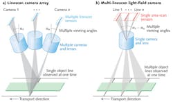
To obtain 3D information, approaches such as multi-camera arrays, time-of-flight sensors, or laser triangulation methods are being employed in machine vision. Figure 1a shows a typical multi-camera setup providing data suitable for 3D reconstruction in a linescan process. In this case, several cameras are observing each point of the imaged object line from several angles at the same time; i.e., a 3D light field is recorded.
The proposed multi-line light-field acquisition setup takes an alternative, more rigid approach to the acquisition of a 3D light field-because of the motion between observer and object, a single multi-line camera observes the same object line from different angles in different time instances (see Fig. 1b). This camera essentially acts as a fast area-scan camera equipped with a standard lens system recording a 3D light field over time.
Computational imaging for multi-linescan light fields
Light fields, as provided by the multi-line-scan light-field camera described in the previous section, can be represented by means of epipolar plane images (EPIs). EPIs are sagittal slices through a data structure called a view stack, i.e., a stack of images of the same scene observed from a defined range of angles. Figure 2a shows a simple scene (consisting of two blocks on top of each other) acquired by our multi-linescan light-field camera along with the corresponding EPI stack.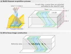
Depending on the distance between camera and each individual observed point, the tilts of the corresponding linear structures in EPIs change. Consequently, the integration along different slopes in EPIs allows for computational refocusing to virtual focal planes different from the original focal plane of the camera.
Exploiting this phenomenon the other way round-through detection of the predominant orientations of the EPI structures—one is able to assess distances in which corresponding object points would get focused. Furthermore, if the EPI-based local estimation of the predominant orientations is combined with the integration along the estimated slopes in EPIs, all-in-focus intensity or color images can be generated, as shown in Fig. 2b. A dense depth map, which can easily be derived from the estimated slopes, is just a byproduct of this process.
A number of strategies for determining predominant orientations in EPIs exist. Most of them are based on so-called slope hypothesis testing, in which a set of slope hypotheses are verified in every pixel location of a reference view (e.g., the central or straight vertical view). A winning hypothesis is then identified according to some criteria reflecting how well the tested slope matches with the pattern in the EPI domain.
A popular but computationally intensive approach to define a criterion for slope hypothesis testing is block matching (BM) in the image spatial domain. In the BM algorithm, image patches extracted from individual views along the hypothesized slopes are compared with each other (or alternatively just with respect to the patch in the reference view). A depth estimate is then delivered by the slope providing the most coherent set of patterns. An example of a depth map generated by the BM method along with a tentative 3D visualization is shown in Fig. 3.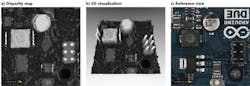
A different strategy for detecting linear structures in EPIs approaches the problem from a statistical perspective: through the estimation of structure tensor (ST). The ST method is capable of estimating principal orientations without the necessity of testing multiple hypotheses in each object point, thus operating in a computationally friendly way. Nevertheless, this method tends to provide less stable results in the presence of noise or illumination variation between different views. To diminish these disturbances, different semi-global or global optimization strategies are usually considered, which, in the end, render such methods less suitable for real-time applications.
Finally, by exploiting the fact that light fields inherently allow for refocusing to virtual focal planes, shape-from-focus (SfF) approaches become applicable. In SfF, some sharpness measure is assessed locally in a virtual focus stack, i.e., a set of computationally refocused images that correspond to different but known focal distances. Afterward, an estimation of depth is obtained in each pixel from the maximum sharpness value detected over all virtual focal planes. The SfF method is computationally highly efficient and, moreover, it can easily be combined with alternative approaches such as the BM method. A fusion of SfF with image or structure matching usually delivers enhanced robustness in EPI slope estimation.
Light-field-improved TDI
Time delay and integration (TDI) is a widely used technique in machine vision to increase the signal-to-noise ratio (SNR) at higher acquisition speeds. Using TDI, each object point is imaged multiple (n) times, which allows for the theoretical improvement of SNR by factor of n through summation of signal charges, in the case of CCD-TDI sensors. In the case of CMOS-TDI sensors, the improvement by about a factor of √n is achievable through summation of signal currents or voltages.
The summation of signals assumed in TDI neglects the different observation angles for individual observations and ignores the 3D information that is inherently contained in the acquired data. Using the light-field representation, one is able to computationally focus to varying focal planes at each individual pixel, whereas TDI is restricted to a single focal plane.
Light-field-improved TDI is equivalent to conventional TDI for flat objects residing strictly in the focal plane and perfect synchronization of transport and acquisition speed. When an object departs from the DoF range, a depth-related blur becomes visible in TDI images. Similarly, in the case of loose synchronicity between transport and acquisition, TDI suffers from motion blur. Both sources of blur are reflected in the EPI structure and can be compensated by computational imaging.
Using the methods described previously, an all-in-focus image can be computed that differs from a TDI image. Unlike the TDI case, the summations leading to an all-in-focus image are performed adaptively along estimated slopes in EPIs, which results in correct treatment of all repeated acquisitions of each individual object point regardless of its distance from the camera. Figure 4 shows an image of a PCB board acquired by our multi-linescan approach and derived TDI image, as well as the corresponding all-in-focus image.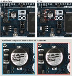
Apart from the improved TDI, which is able to cope with blur induced by varying depth and motion, the proposed light-field approach offers industrial inspection based on 2.5/3D information for fine surface structures and non-flat objects. An important advantage of this method is that the setup is very compact and uses standard hardware components. Furthermore, the proposed light-field processing is highly suitable for pipelined or parallel computation.
References
1. R. Ng et al., "Light field photography with a hand-held plenoptic camera," Tech. Rep. CSTR2005-02, Stanford Univ. (Apr. 2005).
2. C. Perwaß and L. Wietzke, "Single lens 3D-camera with extended depth-of-field," Proc. SPIE, 8291, 829108 (2012).
3. B. Hayes, "Computational photography," American Scientist, 96, 2, 94–99 (Mar.-Apr. 2008).
4. S. Štolc, "Depth and all-in-focus images obtained by multi-line-scan light-field approach," Proc. SPIE, 9024, 902407 (2014).
5. S. Wanner and B. Goldluecke, "Globally consistent depth labeling of 4D light fields," Proc. CVPR, 41–48 (June 2012).
6. S.K. Nayar and Y. Nakagawa, "Shape from focus," IEEE TPAMI, 16, 8, 824–831 (Aug. 1994).
7. H. Xing-Fei and O. Nixon, "Time delay integration speeds up imaging," Photonics Spectra (May 2012).
Svorad Štolc and Reinhold Huber-Mörk work in the Intelligent Vision Systems research area at the Department of Safety & Security of the AIT Austrian Institute of Technology GmbH; e-mail: [email protected]; www.ait.ac.at/departments/safety-security/research-areas/intelligent-vision-systems/?L=1