Motion Control: Software supports multiple optical fiber alignment options
GUY BOUVREE and BEDA ESPINOZA
Optical fiber is essential to support the current demands on data-transmission devices in networking and mobile applications for high-data packets and fast-data transmission. Supporting this trend, manufacturers are creating smaller multichannel devices. Consequently, the optical fiber alignment systems used in production must be flexible enough to accommodate various configurations of these devices based on light sources, number of channels, types of detectors, and vision systems. The alignment system must also be sophisticated enough to detect issues at the beginning of the process to eliminate downstream costs.
To meet these challenges, GBC&S developed a software package, Apgee, that can be configured for multiaxis fiber alignment starting with simple xyz stages to more complex geometries like hexapods and even configurations with 12 axes and load/unload features. Additional configurations can also be set up based on the motor type, a selection of alignment algorithms, and video capabilities. To illustrate the full demands placed on fiber alignment software and hardware, we will describe three generic optical devices and the alignment challenges that must be managed.
Fiber alignment challenges
The goal of fiber (or optical) alignment is to find the location of the maximum amount of light passing through all devices and components. The first challenge is to find the beam, and the next challenge is to find the position where this beam is at its highest peak. This generally employs hardware that has the appropriate Minimum Incremental Motion to resolve the position relative to the power level and the speed to perform the search algorithms as fast as possible.
Depending on the complexity of the final device, fiber alignment may require from 3 to 16 axes of motion, a power detector and meter, and up to several vision sensors. In addition, some axes will be more critical than others, so that different types of motion stages and the associated controller may have to be mixed and matched to create the most efficient and cost effective fiber alignment solution.
The ideal software must be able to implement these algorithms and, at the same time, be compatible with motion controllers, power detectors, and vision sensors. Another important feature is the ability to monitor the results and present the data in a form that is easily understood and intuitive.
The following three examples of device configurations are typically found in fiber alignment applications: 1) simple single-channel, single-ended configuration, 2) single-channel, double-ended configuration, and 3) multichannel, double-ended grating configuration.
Each presents its own challenges, from the optimization process to the actual integration of the various hardware needed to efficiently perform the alignment, then move on to the next step in the process, which is joining (i.e., welding or gluing). It is important that the alignment step is accomplished as near perfect as possible to reduce losses in the downstream processes.
Single-channel, single-ended fiber alignment
This is the simplest configuration of a fiber alignment system requirement, in which a single-channel device is aligned to another single-channel device. Typically, these are single-mode fibers, with well known optical transmission properties.
The alignment process starts with an algorithm to find the transmitted light in rough increments, and a more definite algorithm is executed to search for the maximum location of the beam. In this case, the search may start with a raster scan and then finalize this with a dichotomy scan.
A raster scan can simply be around the xy plane, indexing on one axis and scanning in the other. The raster scan stops when light is detected. A dichotomy algorithm moves in discrete steps in one axis and continues along this direction while the power signal is increasing. Otherwise, the algorithm steps back from that axis direction and moves on in the other direction.
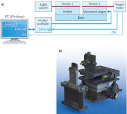
Figure 1a is a schematic of the hardware used in this configuration, the control paths between the motion controller and power meter, and communication with the software. Figure 1b shows an example of an actual system using Newport motion products.
Single-channel, double-ended fiber alignment
The next configuration example, with a double-ended device, is more complicated. Double-ended devices transmit the signal from one interface to another. As with single-mode fibers with known optical transmission properties, the process is similar except for the need to roughly align the left and right ends of the device.
This can be accomplished with video assistance and is meant to be done the first time the device is used, as a starting point. Eventually, if devices are consistent between units, video assistance will not be needed in the process. From here, the same search algorithms can be used as in the first configuration but performed twice, once at the left end, then applied on the right end of the device.
Figure 2 shows a schematic of the hardware used in this configuration, the control paths between the motion controller and power meter, and communication with the software. The software will execute the search algorithms independently for each side of the device. Not shown is the video signal path that can also be displayed through the Apogee software.Multichannel, single-ended fiber alignment
The third configuration deals with multiple single-ended channels. The challenge for this configuration is to first determine whether to maximize the power at all channels or use the average. Clearly, maximizing the power output at each channel is the ideal situation, but it may not be practical due to the time it would take. Therefore, averaging the optimum power among the channels is implemented in this configuration.
Start with a spiral algorithm to first find the beam in the first channel. Once the beam is found on Channel 1, a raster scan to find the beam at the last channel is implemented. Next, a dichotomy search will be executed to find the maximum beam power location. At this point, an angular adjustment is needed to align the channels, and another dichotomy search will be done to find the highest maximum power among all channels.
Figure 3 shows a schematic of the hardware used in this configuration with the capability to utilize two detectors/power meters. The software will execute the search algorithms independently for first and last channels as well as the average among all the channels.Other fiber alignment configurations
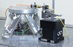
Other possible fiber alignment configurations are: 1) single-channel to multichannel, single-ended (single or multimode fibers) and 2) single-channel, single ended with critical angle measurements. The latter requires tip/tilt adjustments and is best addressed with an HXP hexapod rather than xyz stage stacks (see Fig. 4). Newport HXPs have the advantage of two programmable pivot points for precise angular alignment at the channel surface.In addition to the raster and dichotomy algorithms, other algorithms must be available from the software, wherein a user can choose them individually or in combination, to optimize the search times. Here are some additional algorithms that can be implemented depending on the properties of the device:
- Algorithms to find the light: 1) spiral (in xy, xz or yz planes)—with programmable step size and maximum distance from center, and 2) video-assisted positioning—after pixel size calibration, it allows the user to position the fiber near the device by just clicking on the video image
- Algorithms to optimize the location: Escalade—after executing two small raster scans, move the fiber along the third axis to increase the signal.
When considering the total process for optical-fiber-based device manufacturing, fiber alignment is one important step. To enable a complete solution, interfacing to other hardware is just as important. For example, the ability to control robots, glue dispensers, and UV curing lamps will enhance the usability of the software downstream of the process.
Based on the varying requirements to assemble these optical devices, there is no standard hardware and software solution that addresses all requirements. On the other hand, Apogee has the capability to support different configurations of devices (single vs multichannel, single vs double-ended, single vs multimode), varying motion control requirements (low-cost to high-end, stacked stages to the hexapod), detectors, and vision sensors. Apogee also has the flexibility to be configured and reconfigured as the devices change or the process is updated.
Guy Bouvree is principal at GBC&S Consulting Services, 2 Rue Helene Boucher 77170, Brie Compte Robert, France; [email protected]; and Beda Espinoza is the product marketing manager for Motion Newport, 1791 Deere Ave., Irvine, CA 92606; e-mail: [email protected]; www.newport.com.


