LASER DIODE AND VCSEL TEST: High-throughput DC production test techniques for laser-diode modules and VCSELs
DALE CIGOY
Staying competitive in the laser-diode (LD) and vertical-cavity surface-emitting laser (VCSEL) markets demand cost-effective production test strategies. The value-added nature of each step in manufacturing dictates testing each component prior to the next assembly step. For example, the cost of scrapping a complete laser module due to a failed back-facet monitor photodiode is much greater than the cost of providing 100% testing of the photodiode component prior to assembly. This article offers an overview of high-speed DC test tools and techniques that can help these manufacturers test their products more efficiently.
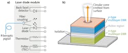
A typical LD module consists of a laser diode and a back-facet monitor photodiode. Temperature-controlled LD modules also include a thermoelectric controller (TEC) and a thermistor to allow precise regulation of the module's operating temperature. High-speed LD modules may also carry an integrated modulator chip. Although a VCSEL has a more complicated semiconductor structure than a standard LD, it typically has a less complicated package (see Fig. 1). Unlike edge-emitting laser diodes, VCSELs can be tested "on wafer."
During DC testing, the specifications of interest for the typical LD or VCSEL module include (L = light output; I = current):
- Laser forward voltage
- Kink test or slope efficiency (dL/dI)
- Threshold current
- Monitor (back facet) reverse-bias voltage
- Monitor (back facet) current
- Monitor (back facet) dark current
- Optical output power
LIV test sweep
Forward voltage test. The forward voltage (VF) test verifies the forward DC characteristics of the LD. Current (IF) is swept, and voltage drop across the LD is measured. Some high-power LDs may require IF sweeps up to 2–3 A, usually in increments of 1 mA. Most need sweeps up to 1 A, with 0.5 mA or 0.25 mA steps. Time per test sweep should be in the range of a few milliseconds. The typical measurement range is 0–10 V, and microvolt-level resolution is required. VCSELs are typically lower-powered devices requiring IF sweeps up to 30 mA with current steps of 1 μA. This test requires the use of one channel of a dual-channel source-measure-unit (SMU) instrument to source current to the laser and measure the corresponding voltage drop. (An SMU instrument provides a precise and user-controllable source of current and voltage.)
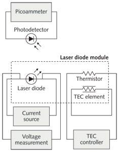
Light-intensity measurement. Light-intensity (L) measurements verify the light output of the LD. Light output power increases as drive current is increased, and the output of this test is usually displayed in milliwatts. For DC-based light measurement, a reverse-biased photodiode is exposed to the output of the laser diode. This radiation is absorbed, and a current is produced by the detector. This resulting photodiode DC current is measured with a picoammeter or electrometer. However, the photocurrent can also be measured with an SMU as long it offers an acceptable low current measurement range. Typically, a measurement range of 100 nA is more than adequate for many lasers. The returned photocurrent can then be used to determine the optical power of the device under test. Optical power measurements require a calibrated detector or integrating sphere. The calibration information, or responsivity (R), is a wavelength-dependent value determined during the calibration process.
This equation is used to calculate the optical power from a photocurrent:
L = Ip/R
where L = optical power of the light source (W), Ip = current from the detector, and R = responsivity of the detector at the wavelength of choice (A/W). The responsivity curve is provided when the detector or sphere/detector assembly has been calibrated.
Thus, the current measured by the detector is divided by the responsivity of the detector at the wavelength of interest. The result is the optical power impinging on the detector.
Lasing threshold current test. The threshold current is the current at which the LD starts lasing. The second-derivative technique is one method for determining this threshold current, which is defined as the first maximum of the second derivative of the light output and is a calculation based on L.
Back-facet monitor diode (BFMD) test. This test verifies the response of the back-facet detector photodiode (also reverse-biased) to increase light output of the LD as the drive current is increased. Typical current measurement range is 0–100 mA, and the required resolution is 0.1 mA. Although this measurement is typically performed with a picoammeter or electrometer, an SMU can be used instead if it offers a low enough current measurement range. Typically, a measurement range of 100 nA is more than adequate for low-powered optical devices. In this test, the second SMU channel of a dual-channel SMU can be used to bias the photodetector (if needed) and measure the photocurrent simultaneously. Or, a single-channel SMU or a simple picoammeter can measure the back facet photocurrent.
Kink test/slope efficiency. This test verifies the proportionality of the relationship between the drive current (IF) and L as depicted in Fig. 3. The relationship between IF and L should be linear about the nominal operating range. If the relationship is truly linear over the tested range, the first derivative of the curve will be a nearly horizontal line. This is graphed as dL/dIF. The first derivative will tend to amplify any bumps or kinks in the light/current (L-I) curve. If this curve has any significant "kinks" (the curve does not appear smooth), the laser is considered defective. If operated at the IF value corresponding to the kink, the light output will not be proportional. The maximum value of the second derivative of the L vs. IF curve can be used to calculate the threshold current, which is the value of the drive current at which the LD starts lasing. The kink and slope efficiency of a particular device are also calculations based on the analysis of L.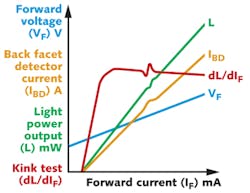
Temperature testing. The LIV test is often performed at multiple laser-diode temperatures, such as at both the nominal temperature and the extremes of the device specification. Another common strategy is to test at several temperatures, then analyze these families of LIV curves to ensure the device meets the specification.
Test-system configuration
Figure 4 shows an LIV test system configuration that includes a two-channel SMU, a specialized 50 W autotuning SMU instrument, and a computer (PC) equipped with a GPIB interface card.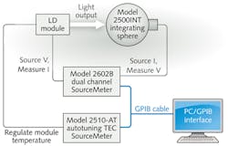
Each channel of the two-channel SMU can source either a voltage or current and simultaneously measure voltage and current. This offers great convenience for LIV testing by allowing one SMU channel to source current to the device under test (DUT) and measure the voltage while the other channel is monitoring the photocurrent of the detector near the DUT.
With many instruments, the PC controls all aspects of the test. In each element of a test sequence, the instruments must be configured for each test, perform the desired action, and then return the data to the controlling PC. The controlling PC then must evaluate the pass/fail criteria and perform the appropriate action for binning the device under test. Each command sent and executed consumes precious production time and lowers throughput. In this scenario, a large percentage of this test sequence is consumed by communicating information to and from the PC. However, recent advances in SMU architecture are beginning to eliminate these communications delays.
The latest generation of SMUs, like Keithley's Series 2600B System SourceMeter SMU instruments, can increase the throughput of complicated test sequences dramatically by decreasing the amount of traffic over the communications bus. The majority of the test sequence is embedded in the instrument itself. The Test Script Processor (TSP) is a full-featured test sequence engine that allows control of the test sequence, with internal pass/fail criteria, math, calculations, and control of digital I/O. The TSP can store a user-defined test sequence in memory and execute it on command. This limits the set-up and configuration time for each step in the test sequence and increases throughput by lessening the amount of communications to and from the instrument and PC.
Recent advances in SMU architecture can speed and simplify the module testing process; for more information, download the application note "High Throughput DC Production Testing of Laser Diode Modules and VCSELs" at http://keithley.com/data?asset=50303.
ACKNOWLEDGEMENT
Series 2600B System SourceMeter SMU instruments are a registered trademark of Keithley Instruments.
Dale Cigoy is a lead applications engineer for Keithley Instruments, Inc., a part of the Tektronix test and measurement group, Cleveland, OH; e-mail: [email protected]; www.keithley.com.