LASER BEAM COMBINERS: Apodized combiner packs in the laser-diode beams
One of the hottest areas in lasers now is the use of incoherent beam combining to create very high-power laser diode systems. Such systems are used directly for applications such as laser machining and welding, or for pumping of large solid-state lasers. They’re also used as input to fiber-delivered, “direct-diode” high-power light sources.
But laser diodes have larger spectral linewidths than most nondiode lasers (high-power laser diodes also have a large multimode emission area, further complicating beam combination). As a result, brightnesses achieved by incoherent beam combining via wavelength-division multiplexing (WDM) reach an unsatisfyingly low limit. This is a soft limit, however, in that novel beam-combination designs are continually being created that go further in getting just that little bit extra.
However, researchers at Aachen University and the Fraunhofer Institute for Laser Technology (ILT; both in Aachen, Germany) say they have devised a method of WDM beam combining for laser diodes that can increase the spectral brightness (and thus the number of lines that can be crammed into a certain spectral width) over other methods by a factor of approximately six—certainly no incremental improvement.1 So far, though, the group has only done computer simulations of the technique.
Apodized gratings
The approach is based on the sometimes-used WDM volume holographic grating (VHG), which is a transparent volume that contains a number of phase gratings, each of which handles a different wavelength. The phase gratings are each created by interfering two laser beams to create an exposure in the photoactive grating material. If done right, the VHG takes many separate input beams and produces a single, combined output beam.
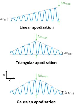
In addition to a central high-efficiency spectral peak, however, each grating also has spectral side lobes; these limit how close in wavelength two laser diodes can be, and thus how many can be spectrally combined. The Aachen researchers minimize the problem by using apodized gratings, which can, for example, be created in the photoactive material by interfering two Gaussian beams.
The researchers refine the technique by altering the exposure beam cross-sections, making them elliptical rather than circular. They model the resulting gratings using the theory of propagation of optical waves in layered media, creating a transmission matrix that can take into account local grating defects and wavefront-adapted grating layers. The researchers cite these as advantages over couple-wave analysis (an alternate approach).
The continuously varying refractive index is discretized for the model. Within each layer, a propagation matrix describes the movement of light within and transmission matrices set the boundary conditions between it and the adjacent layers.
0.34 nm wavelength spacing
For a 976 nm Bragg wavelength, models of both apodized and conventional beam-combining VHGs were created, assuming a Bragg angle of 15° and a peak efficiency of 90%. The apodized grating had a thickness of 3.1 mm and a Gaussian beam waist of 1.6 mm; the standard grating has a thickness of 2 mm.
While the side-lobe suppression (difference between the central and side lobes) for the standard grating was 7 dB, this difference increased to 22 dB for the modeled apodized grating. As a result, the conventional VHG allowed a laser wavelength spacing of 2 nm; for the same conditions (a side lobe of 1% diffraction efficiency coinciding with the central peak), the apodized VHG allowed a wavelength spacing of only 0.34 nm.
Calculations were done for different types of apodization functions (see figure). While Gaussian apodization can produce a side-lobe suppression up to 63 dB, triangular apodization leads to 22 dB and linear apodization to no suppression at all. To produce a Gaussian apodization with a 63 dB side-lobe suppression, however, the grating must be made three times thicker than a conventional grating.
REFERENCE
1. S. Nippgen et al., Opt. Lett., 37, 24, 5205 (Dec. 15, 2012).
About the Author
John Wallace
Senior Technical Editor (1998-2022)
John Wallace was with Laser Focus World for nearly 25 years, retiring in late June 2022. He obtained a bachelor's degree in mechanical engineering and physics at Rutgers University and a master's in optical engineering at the University of Rochester. Before becoming an editor, John worked as an engineer at RCA, Exxon, Eastman Kodak, and GCA Corporation.

