MOLECULAR IMAGING: Optical system design improves fluorescence light capture
CHRISTOPHER COTTON
Fluorescence microscopy is used in a wide range of medical and biological applications, and recent improvements in image quality are extending the number of applications. However, life science companies using this technique to investigate complex molecular and cellular structures still encounter significant obstacles to acquiring information from the sample.
Their optical designs must provide effective illumination, sufficient filtering to isolate the fluorescent light from the illumination without signal loss, and efficient collection of light from the sample. Improving system performance can mean reduced sample size, as well as earlier and more accurate testing.
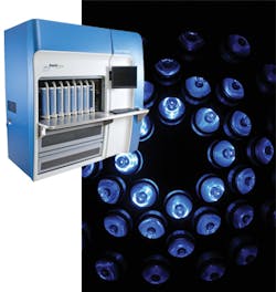
ASE Optics works with life science companies to improve optical system design and identify novel techniques to speed research and reduce risk for systems such as the Growth Direct System by Rapid Micro Biosystems (Bedford, MA). While the microbiology method of testing has not changed since the times of Louis Pasteur, new test systems like the Growth Direct System automate and speed testing, shortening grow time and shrinking needed sample size (see frontis, this page).
Optical fluorescence is a phenomenon that occurs when a molecule absorbs excitation light at a wavelength within its absorption band and then, nearly instantaneously, emits light at a longer wavelength within its emission band. A fluorophore is often applied to the sample to bind to the specific molecules or cellular structures that need to be identified in testing. In many cases the fluorophore occurs naturally in the molecules or cellular structures that are being investigated. An optical fluorescence system design needs to:
• illuminate the sample with excitation light
• efficiently collect light emitted from the sample
• reject scattered excitation light before it reaches the detector
The filter problem
The arrangement of filters is intended to isolate the bright excitation light from the path of the weak emitted light. Fluorescence lines for the emitted light can be very narrow, requiring highly accurate filter specification and design. Advances in thin-film optical filters have significantly advanced fluorescence microscopy, but their use presents challenges: cost and angular sensitivity.
The wavelength transmission characteristics of thin-film filters will vary with incident angle. The collection efficiency of systems with a large field-of-view, a high numerical aperture (NA), and a narrow distance between the excitation and emission wavelengths will be limited by the size and angular acceptance of the filter.
A common layout for a fluorescence imaging system is to have the excitation light injected into the system in an area where the light can be collimated. In this arrangement, the beamsplitter selectively reflects the excitation light from the light source to the sample and transmits the emission light from the sample toward the sensing system. The beamsplitter will place a lower limit for how close together the excitation and emission wavelengths can be.
By locating the beamsplitter in an area where the image light can be collimated, we avoid introducing aberrations into the illumination and imaging paths, which will appear when a tilted plate is introduced in either a converging or diverging ray fan.
Alternate illumination approach
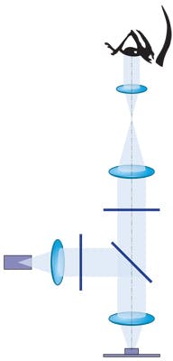
In designing the optical system for the Growth Direct System, the ASE Optics engineering team helped to optimize an alternate approach (see Fig. 2). The illumination approach was key to achieving the required performance: The blue light that causes the cells to fluoresce allows the sensor to identify fluorescence from just 100 cells vs. the nearly 5 million cells needed for the human eye to see colonies.To improve the overall efficiency of collected fluorescence, the optical system design eliminated the need for the beamsplitter. This scheme still presented performance challenges. The illumination source is provided by an array of several dozen blue LEDs arranged in a pattern that provides uniform light and optimizes the aspect ratio of the excitation energy to help simplify the imaging problem. Each LED has a corresponding microlens and filter for directing its narrowband energy toward the sample.
A single long-wavelength pass filter then transmits the fluoresced light and rejects the excitation wavelengths from the imaging path. The sample light still has high etendue that must be handled by the filter. However, this light is incident at angles about normal—not angles centered about 45° as in a standard system. This helps to reduce the cost and performance requirements on the filter without compromising the quality of the data obtained from the sample.
Proper materials selection
There are also considerations for providing suitable materials for optical components in the fluoroscopy environment. When illuminated with ultraviolet light, some types of optical glass exhibit fluorescence at particular wavelengths, primarily caused by impurities within the glass or incorrect choices for optical adhesives.
Using materials that fluoresce complicates the task of filtering and adds unwanted noise to the sensed light signal. In many cases in which the ASE Optics engineering team was engaged to specify optical components with best-fit materials, crystals, high-purity optical materials, and nonfluorescing cements have enabled our customers to reduce the overall system noise due to optical sources.
Once the correct illumination sources and filter configuration had been chosen, we could ensure performance of the imaging lens with the proper optical design and packaging. Often the imaging lens performance is overlooked in fluorescence imaging systems until the first one is built. The availability of high-pixel-count cameras enables the collection of significant amounts of data from a single image; however, as the amount of information increases, so does lens complexity.
Fluorescence microscopy in practice
The availability of high-purity optical materials like fused silica, Cleartran, and other crystalline materials; the expanding use of LEDs; availability of off-the-shelf thin-film filters; and advanced assembly techniques has broadened the applications for fluorescence microscopy, bringing it from the research lab to the manufacturing floor.
Rapid Micro Biosystems' Growth Direct System is used by filterable pharmaceutical companies to conduct microbiology testing that would have previously been done via Petri dish with growth observed by microbiologists. Through the use of the optical system, Rapid Micro Biosystems has been able to deliver results in half the time of traditional microbial test methods. The end result? Faster moving product and reduced risk for the pharmaceutical companies, as well as safer products for consumers.
Christopher Cotton is general manager of ASE Optics, LLC, 850 John Street, West Henrietta, NY 14586; e-mail: [email protected]; www.aseoptics.com.


