SOFTWARE & COMPUTING: Computer modeling optimizes thin-film coating uniformity
WILLIAM H. SOUTHWELL AND JOSEPH E. PEEPLES
Coating uniformity is vital for high yields in thin-film coating fabrication processes, especially as coating requirements become tighter and as production volumes increase to reduce costs and remain competitive. A new software utility tool has been developed that models and predicts coating uniformity for various sources and planetary motions. When chamber configuration geometry design is insufficient for adequate uniformity, masks may be designed and optimized to improve coating uniformity as a function of source position, planetary gear ratios, and other chamber parameters.
Thin-film coating basics
The fabrication of multilayer optical interference coatings is a particularly difficult task. All of the layers must have uniform thickness over a single part and over all the parts being deposited in a single coating deposition step, especially to obtain the desired spectral response of a thin-film filter, for example.1 Most deposition sources will deposit on surfaces with a direct line-of-sight view of the substrate being coated. The increment of deposition thickness in an incremental time element depends on the length of the line-of-sight ray and the angle this ray makes with the source normal and substrate normal.
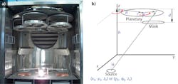
Thin-film coating chambers come in various sizes and shapes, but many are characterized by boxes with evaporative sources near the floor and planetary mounts rotating above them, bringing the substrates in and out of the depositing plume. Rotating the parts greatly improves the thickness uniformity across all filters attached to the planetary.2 Just how uniform the various parts on the planetary become is a function of the chamber geometry and the planetary motion (see Fig. 1).
Achieving good coating uniformity is typically a lengthy iterative process. Quantitatively determining uniformity involves populating the planetary with small samples, performing a single-layer deposition with enough thickness to have some ripples in the transmittance or reflectance spectra, and then spectrally measuring each part. The shift in the wavelength positions of the ripple peaks or valleys is a measure of the coating uniformity.
With rapidly rotating planetary motion, the uniformity is fortunately radial regardless of the source distribution. Uniformity is usually normalized to the center of the planetary; that is, thickness across the planetary divided by the thickness at the center forms the uniformity curve. With the uniformity known, a mask is configured (usually by experience and trial and error), installed, and the uniformity measurement is repeated.
A common mask shape looks like a leaf and is fixed in place under the moving planetary. The purpose of the mask is to block some of the deposition in regions where the coating is too thick; however, the mask cannot add thickness, it can only reduce deposition. Since generally all points on the planetary will pass over the mask, the trick is to find the mask shape that will retard the deposition in the high spots to improve uniformity. Furthermore, since the mask reduces deposition, the deposition will take longer. Thus, mask efficiency as measured by how much less is being deposited as compared to the case without a mask is an important parameter in mask design.
In the next step for improved uniformity, the mask is trimmed. This step is difficult because the mask is only decreased in size and it is hard to know where and how much to trim to change the material distribution in a certain region. In addition, this mask-trimming process typically results in residual nonuniformity because the convergence of this technique depends too much on the shape of the starting mask and its position in the chamber. Source position is also a factor for convergence.
A software tool from Table Mountain Optics called UniformityPro enables the calculation of coating uniformity for given chamber configurations, including the presence of one or more masks. The software also allows for optimizing the shape and position of the mask to improve uniformity. In addition, it can improve uniformity while maintaining good efficiency.
Plume distribution
Of foremost importance in this new software modeling process is knowledge of the plume distribution. The most widely used model is the cosine to the mth power, or cosmθ. The value m = 0 has no angular dependence and hence the evaporant behaves as a point source. More commonly, m = 1 represents an extended source emulating from a small region. Higher values of m show a more peaked distribution, and noninteger values of m are also used.
When the plume distribution is not known, then it should be measured in order for the modeling to have validity. It is this measurement that anchors the code to reality. The plume distribution may be measured by positioning several small parts on a nonrotating and stationary planetary above the source. Then, deposit a single layer on known substrates and measure the layer thickness of each part, which has been identified by its x, y, z position relative to the source. Then fit the value of m to best fit the measurements, properly accounting for the source and substrate normal angles and radial (R squared) effects in the calculation.
The UniformityPro software has a menu option that opens a data grid allowing these measurements to be entered manually or pasted from a spreadsheet. The height of the planetary and the x, y positions and the corresponding thicknesses are entered. When the Fit m button is clicked, the best fit value of m is displayed.
Modeling parameters
The inputs to the UniformityPro software code are the geometric chamber parameters: h is the height of the planetary plane above the chamber floor; x, y, and z is the position of the source relative to the center of the chamber floor (optionally the source position may be entered as ρ and φ polar coordinates); R is the radial position of the center of the planetary; r is the radius of the planetary; and g is the gear ratio of the planetary (optionally, this may be entered as the number of sun gear cogs divided by the number of planetary cogs). For convenience, the chamber units are in inches.
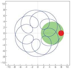
For plots of the trajectory of a point on the planetary, one inputs rP, the radial position on the planetary to show in the trajectory plot, and NP, the number of rotations of the center of the planetary. These numbers are also used in the computation of the uniformity.
Masks
Currently there are three shapes used for optimization masks: a leaf, conic, and an arbitrary form constructed from a table of general coordinates. Any number of masks may be modeled.
The leaf mask looks like a leaf but is a symmetrical parabola. Its parameters include the radial position of the inner tip of the leaf (rL), ΨL the angular position of the inner tip of the leaf (in degrees), L or the length of the leaf mask, and the full width of the leaf mask W.
The conic mask is defined by a set of parameters as a parabola, circle, ellipse, or hyperbola in ray-tracing terminology. The parameters include the curvature c, which is 1 divided by the radius of curvature at the vertex, the conic coefficient k (k = -1 for a parabola; k = 0 for a circle; other values are ellipses and hyperbolas), and the coefficients A4, A6, A8, and A10 for the r4, r6, r8, and r10 general aspheric terms, respectively.
The arbitrary form of the mask is constructed from a table of parameters that define the x,y coordinates of points on the upper and lower edge of the mask. This allows arbitrary mask shapes to be entered.
Code features and optimization
The software allows any number of sources to be used. When more than one is used, then relative deposition rates need to be assigned to each one. Each source has its own position and plume distribution, and the code also accepts any number of masks, each with its own position and size parameters (see Fig. 2).The software also has an optimizer that allows uniformity and mask efficiency to be improved by adjusting the parameters that affect it. For example, source position and planetary height may be adjusted to maximize uniformity for any given plume distribution m. The user may click on a check box to have the code also improve the efficiency while improving the uniformity. Without this feature, excellent uniformity may be achieved at the expense of a very large mask requiring much longer deposition times.
Example mask design
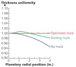
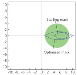
To demonstrate how UniformityPro can optimize coating uniformity, consider a coating chamber with the source x-position at 8 in., h = 12 in., R = 5 in., and with a planetary radius of 4 in. (8-in.-diameter). The computed uniformity of this configuration is 2.46% (see Fig. 3). Next, a leaf mask is added with a 4 in. starting position, 5 in. length, and 2 in. width. The addition of this mask improves the uniformity to 0.81%. This mask shape was determined by manually adjusting the mask width, length, and noting the uniformity curve as these changes are made. The user can fairly easily obtain 1% uniformity in this fashion. We then let the optimizer software adjust the position, length, and width of the mask, which dramatically improved the uniformity to 0.08%.Furthermore, when the starting mask is compared to the optimized mask, it becomes obvious that trimming the mask would never have produced its final optimized form (see Fig. 4). In short, the UniformityPro software eliminates the long process of guessing at mask shapes and positions and iteratively trimming them after depositions; the optimized mask shape can even be printed out with real dimensions. The details of the selected mask can also be exported to a .SCR (AutoCAD) file.
REFERENCES
1. A. Macleod, "Coating Uniformity," Bulletin, Society of Vacuum Coaters, 32 (Spring 2007).
2. A. Macleod, "Layer Uniformity and Thickness Monitoring," Thin-Film Optical Filters, Fourth Edition, 595, CRC Press (2010).
William H. Southwell is owner and Joseph E. Peeples is software developer at Table Mountain Optics, 509 Marin Street, Suite 125, Thousand Oaks, CA 91360; e-mail: [email protected]; www.tablemountainoptics.com.


