FIBER BRAGG GRATINGS: Teflon patch increases FBG accelerometer sensitivity
The fiber-Bragg-grating (FBG) accelerometer—a small, rugged, electromagnetic-field-interference (EMI)-free device used for measuring strains in bridges and other architectural structures as well as seismic shifts in rock—is getting a simple modification that increases its sensitivity by a factor of three. Details of the modification, first modeled using finite-element analysis and then confirmed by experiment, were presented at the 2012 COMSOL Conference India (Nov. 2–3, 2012; Bangalore, India) by researchers at the Central Glass and Ceramic Research Institute, Council of Scientific and Industrial Research (CSIR; Kolkata, India).
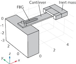
A typical FBG accelerometer consists of a flexible cantilever with an FBG attached to the cantilever near one end and a mass mounted on the other end. When the device is moved, the cantilever bends in proportion to any acceleration in the direction of beam flexure; the resulting strain is measured by the FBG, producing a wavelength shift proportional to acceleration.
High sensitivity is necessary for measuring seismic movements, which are not only usually very small in magnitude but are also low in frequency (for a given magnitude, the acceleration is proportional to frequency). The farther away the FBG sensor is from the cantilever’s neutral axis, the more sensitive it becomes.
A simple patch can be complex
The CSIR researchers move the FBG farther from the axis by placing a patch of material between the FBG and the cantilever. However, there is a limit to how much the sensitivity can be increased this way: First, the patch itself is not perfectly rigid, and thus if made too thick, does not effectively transmit strain to the FBG; second, the patch unavoidably reduces beam flexure, with the amount of reduction depending on patch geometry.
Balancing these two effects to come up with an optimum patch geometry was first done using COMSOL (Burlington, MA) Multiphysics finite-element-analysis software, with the added benefit that sensitivity as a function of cantilever-bending frequency could also be optimized. The modeled cantilever was 40 × 10 × 0.32 mm in size, made of stainless steel, and mounted to an aluminum block (see figure). The FBG was a 4-mm-long section in a 150-μm-diameter polymer-coated silica fiber, and was placed 5 mm from the mounting point of the cantilever.
Three patch materials were modeled: Teflon, polyimide, and aluminum (assumed Young’s moduli for the patch materials were 0.5, 2.5, and 70 GPa, respectively). The patch thickness was varied up to a 2200 μm thickness; a 10 μm thickness of adhesive was also added. The model included frequencies up to 10 Hz. Results of the simulation showed that the FBG sensitivity increased with patch thickness up to a certain point then decreased for larger thicknesses. For a 10 Hz frequency and 1 g acceleration, Teflon achieved the highest simulated strain, followed by polyimide and aluminum.
Modeling optimal FBG placement
The model also showed that strain distribution along the FBG was a symmetric upside-down parabola at its optimum placement at the cantilever’s maximum strain location; any deviation from this optimum placement moved the parabola off center and thus reduced sensitivity.
An experimental version of the accelerometer with a 1000-μm-thick Teflon patch exhibited a sensitivity of 1062 pm/g, which is three times higher than that for a similar device without the patch. The CSIR researchers plan to detail their experimental results in a forthcoming paper.
REFERENCE
1. N. Basumallick et al., “Finite Element Analysis of a Fiber Bragg Grating Accelerometer for Performance Optimization,” Proc. 2012 COMSOL Conf., Bangalore, India.
About the Author

John Wallace
Senior Technical Editor (1998-2022)
John Wallace was with Laser Focus World for nearly 25 years, retiring in late June 2022. He obtained a bachelor's degree in mechanical engineering and physics at Rutgers University and a master's in optical engineering at the University of Rochester. Before becoming an editor, John worked as an engineer at RCA, Exxon, Eastman Kodak, and GCA Corporation.