LARGE OPTICS: Petawatt high-LIDT coatings don't sacrifice performance
Over the past decade, an increasing number of (mainly government-financed) large petawatt laser systems have been built or are planned for construction. The world map of ultrahigh-intensity laser capabilities compiled by C.P.J. Barty (ICUIL 2012) at the National Ignition Facility (Livermore, CA) lists a total of 71 sites that are involved in high-power laser systems, with 16 sites in North America, 30 in Europe, and 25 in Asia.1
In the past, development of such powerful laser systems was hampered by the lack of suitable laser materials, but since the development of chirped pulse amplification (CPA) in the mid-1980s this issue has been overcome for short pulse lengths. Rapid development has taken place in this field, with applications including studies in high-energy-density physics, flash x-radiography, and laser-ignited nuclear fusion.
According to some predictions (ICUIL 2011), the generation of laser intensities of up to 1024 W/cm2 and the generation of gamma-ray pulses of about 100 yoctoseconds (10-22 s) is possible.2 As of 2010, the peak power of the world's most powerful laser (again according to ICUIL 2011) was approximately 11.5 PW, but by the end of 2015 this is planned to increase to approximately 127 PW. In addition, several exawatt-scale projects are currently in the planning stage.
To meet these demands, it is critical to concurrently develop high-performance laser optics that offer high laser-induced damage threshold (LIDT) without sacrificing spectral or phase performance. Although the optics can be made larger to lower the power density, this approach inevitably increases both the size and cost of the system. A compromise must be found, with the LIDT being the key parameter when considering the most appropriate beam size.
Most large-scale petawatt systems are first evaluated in the form of tabletop or smaller-scale demonstration units. As a result, it is of vital importance that all optical components used in the demonstration unit be scalable to the size of the final system, ideally at a nonprohibitive cost. Being able to use the same type of coating for the beam-handling optics throughout the system, regardless of the size of the optics, also makes system modeling much easier.
Evolving needs
CVI Melles Griot's manufacturing facility on the Isle of Man focuses on the manufacture of both small and large high-LIDT precision optics, concentrating on the design and manufacture of large femtosecond optics. To eliminate absorption centers that can cause catastrophic damage, high-LIDT laser optics require both substrate and coatings to be manufactured to the highest standards. In addition, the larger an optic becomes, the more important issues like coating stress also become, especially when dealing with coatings that consist of a large number of layers and are required to function over a wide range of temperatures in air-as well as in vacuum-without performance degradation. Most optics manufactured for these applications require a surface flatness or transmitted wavefront distortion of at least λ/10.
The range of components required when building a petawatt laser encompasses mirrors, windows, beamsplitters, and polarizers; as ever more powerful laser systems have been designed, the coating specifications for all these types of components have changed considerably over time.
For ultrashort (femtosecond or picosecond) laser pulses, the minimum pulse length Δt at a center wavelength λ0 is related to the spectral bandwidth Δλ (at full-width half-maximum, or FWHM) as follows:

where c is the speed of light and K a number related to the pulse shape. For a Gaussian pulse, K equals 0.441. It follows that the shorter the pulse becomes in the temporal domain, the broader the reflected or transmitted spectrum (represented by Δλc in the above equation) is in the frequency (or spectral) domain.
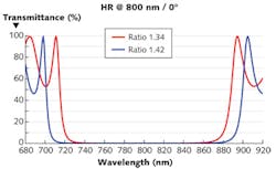
This creates a challenge for the design of optical components, especially those designed to effectively and efficiently manage the effects of dispersion. Traditionally, mirrors for femtosecond lasers use quarter-wave stack designs based on two different materials: one with a low and the other with a high refractive index. The width of the reflectivity band for such coatings is determined by the ratio of the refractive indices of the two materials used to construct the stack (see Fig. 1). While it is possible to find a material combination that can provide sufficiently large bandwidth, not all material combinations result in a coating structure that also offers high enough laser damage thresholds.
Another area of continued development is in polarizers designed for use with femtosecond lasers. For these applications, polarizers must be able to operate over a large range of wavelengths, ideally from 700–900 nm. Standard Brewster-angle plate polarizers typically only operate over a limited bandwidth (a few nanometers) and are not suitable.
Traditional designs center on a plate polarizer that requires the polarizer to be used at an angle of incidence of 70° to 72°. While this is feasible for relatively small beams, for large beam diameters a massive plate polarizer is the result. To ensure an acceptable transmitted wavefront distortion from plate polarizer designs, a high ratio of thickness to diameter is required, with the increasing thickness further reducing the useful aperture. At the same time, the achievable extinction ratios are generally not much better than 5:1.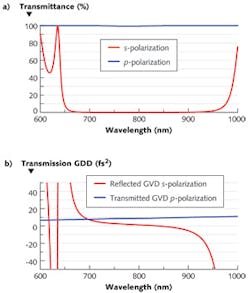
In contrast, optically contacted polarization cubes polarize the incoming beam at an extinction ratio of approximately 500:1 or better over the full 700-900 nm range (see Fig. 3). The p-polarized beam exits the polarizer without any beam deviation, making the component easy to align. These polarizers are also more compact than plate polarizers. For example, a rectangular plate polarizer with dimensions measuring 2 × 6 in. would have to be made approximately 1 in. thick to allow a surface flatness of l/10 and when used at a 70° angle of incidence would only be able to handle a beam smaller than 1.5 in. diameter. In contrast, polarization cubes in sizes up to 76.2 mm can accommodate beams up to approximately 70 mm in diameter (smaller polarization cubes are available for tabletop petawatt laser systems).
REFERENCES
1. ICUIL 2012, web site of the International Committee of Ultra-High Intensity Lasers (accessed June 2012); http://www.icuil.org/events-a-activities/laser-labs.html.
2. IUIL 2011: The International Committee on Ultra-High Intensity Lasers, ICUIL News, 2 (April 2011).
About the Author
Neil Anderson
Technology Development Analyst, Semrock
Neil Anderson is a technology development analyst with Semrock, a unit of IDEX Optics & Photonics (Rochester, NY).
Helmut Kessler, Ph.D.
CTO-Europe, IDEX Optics & Photonics
Helmut Kessler, PhD, is CTO-Europe, at IDEX Optics & Photonics.