SPACE OPTICS: Thermal sieve isolates collimator from cooled test optics
Testing advanced space optics (which virtually all receive collimated light) before launch often requires cryogenic vacuum testing to simulate the space environment. Because apertures for some of these systems can be quite large (like the 6.5 m aperture of the James Webb Space Telescope’s primary mirror), any reduction in complexity of the test setup helps cut costs.
Such a test setup needs to provide collimated light; the conventional way to do this in noncryogenic test is to include a collimator in the vacuum chamber. However, this is not ideal for cryogenic testing, as thermal radiation from the collimator is a problem unless the collimator is kept at the same low temperature as the test optics. Custom collimators designed to work at a precise cryogenic temperature are costly.
A collimator must have a diameter at least as large as the clear aperture of the optics under test. So how can a collimator be “hidden” in a cryogenic vacuum chamber so the optics under test don’t thermally “see” it?
Stacked sieves
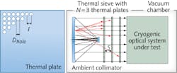
A group of researchers at the University of Arizona (Tucson, AZ) has come up with an approach: a series of spaced plates, each with an identical square array of round holes, called a thermal sieve (see figure).1 The setup, which is placed inside the chamber between the collimator and the optics under test, passes collimated light from the collimator but blocks most thermal radiation emitted by the collimator, since the thermal radiation usually takes paths angularly different from the path of the collimated light. The result is that the collimator itself can be kept at or near the ambient temperature outside the chamber.
Unavoidably, because the array of holes is in essence a 2D diffraction grating, the collimated beam received by the optics under test has multiple diffraction orders. However, all but the zero-order point-spread function produced by the test optics can be ignored.
By careful design and analysis, the thermal sieve can be optimized to reduce the remaining thermal load to the test optics: Parameters to be optimized include the thermal plates’ temperatures and emissivity values, the hole size and spacing, and the number and spacing of plates. For example, the lateral spacing between holes must be small enough that the diffraction orders are separated at the image plane by a distance much greater than the Airy disk size.
An example modeled thermal sieve setup had an outside ambient temperature of 300 K, a cooled temperature of 35 K, a 6.5-m-diameter clear aperture, a 1 μm test-beam wavelength, three plates, 2-mm-diameter sieve holes, and 20 mm lateral hole spacings (for an obscuration ratio of 0.99). The plate nearest the collimator was held at 300 K, the plate nearest the test optics was at 35 K, and the temperature of the middle plate was varied from 150 K to 300 K.
In thermal-load calculations, the higher the emissivities of the two outer plates, the lower the thermal loads were. In contrast, the lower the emissivity of the middle plate, the lower the thermal load [for example, decreasing the middle plate’s emissivity from 0.15 to 0.05 reduced the thermal load (with the middle plate at 280 K) from about 0.6 W/m2 to about 0.2 W/m2].
The relation of thermal load to the plate temperatures was complicated, but the researchers learned that if the middle plate’s temperature was fixed, tweaking the temperatures of the other two plates could optimize the performance of the thermal sieve. Conversely, letting the middle plate’s temperature float showed a best performance point; in both cases, this was when the middle plate reached a temperature of about 252 K.
Analysis showed that the hole-alignment tolerance was more important than the hole-size tolerance for achieving lowest test-beam phase errors. For the assumed tolerances, the rms phase error due to the thermal sieve was under 0.006 waves.
REFERENCE
1. D.W. Kim et al., Opt. Exp., 20, 11, 12378 (May 21, 2012).
About the Author

John Wallace
Senior Technical Editor (1998-2022)
John Wallace was with Laser Focus World for nearly 25 years, retiring in late June 2022. He obtained a bachelor's degree in mechanical engineering and physics at Rutgers University and a master's in optical engineering at the University of Rochester. Before becoming an editor, John worked as an engineer at RCA, Exxon, Eastman Kodak, and GCA Corporation.