FIBER LASERS: Swept fiber laser uses dispersion tuning to target OCT imaging
YUYA TAKUBO and SHINJI YAMASHITA
Fiber lasers are widely used in many telecom, medical, and industrial applications, and wavelength-tunable fiber lasers are very useful for dense wavelength-division multiplexing (DWDM), optical fiber sensing, and test and measurement applications. Conventional wavelength-tunable fiber lasers change wavelength through adjustments to a wavelength-tunable filter (a diffraction grating or fiber Fabry-Perot tunable filter, for example) in the laser cavity. Even though Fourier domain modelocking (FDML) introduced by R. Huber et al. is a strong method for swept-source OCT (SS-OCT) imaging, all these conventional techniques have fundamental limitations of wavelength sweep rate and range as they rely on some kind of mechanical tunable filter.1
Our group at the University of Tokyo has developed a wavelength-tunable fiber laser based on dispersion tuning, a method that enables wavelength sweeping without using any tunable filters. In this method, we apply a modulation signal in a highly dispersive laser cavity and choose the wavelength by controlling the modulation frequency, enabling a sweep rate of more than 200 kHz over a 140 nm sweep range. This performance is significantly better than conventional wavelength-swept fiber lasers.
An important application for tunable fiber lasers is SS-OCT, a noninvasive cross-sectional imaging technique using infrared light that has shallower imaging depth but much higher resolution than competing x-ray tomography and magnetic resonance imaging (MRI) techniques.2 The OCT method is also capable of real-time imaging and is expected to be applied to endoscopic systems and intravascular catheters using optical fiber delivery.
For SS-OCT systems, wavelength-swept fiber lasers with high sweep rate and sweep range are needed. We have applied our dispersion-tuned fiber laser to an SS-OCT system and obtained OCT images at up to 50 kHz, demonstrating the promising potential of these lasers for high-performance OCT imaging applications.
Dispersion tuning
The principle of the dispersion tuning method is modelocking of a dispersive laser cavity. Highly dispersive devices (such as dispersion-compensating fibers) are inserted into the laser cavity and the light in the cavity is intensity modulated. The lasing wavelength changes corresponding to the intensity modulation frequency.3,4
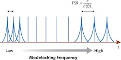
When the light in the laser cavity is intensity modulated at the integral multiple frequency of the free spectral range (FSR), the light is actively modelocked. The FSR of the laser cavity F can be expressed as F = c/nL where L is the cavity length, n is the refractive index in the cavity, and c is the speed of light in a vacuum. When the cavity contains chromatic dispersion, the FSR is a function of wavelength λ or frequency f (see Fig. 1). Ignoring higher-order dispersion, the relationship between the wavelength and the FSR F is expressed as λ = - (n0/cDF0)(F - F0) + λ0 where n0 is the refractive index at λ0 and D is the dispersion parameter.
Active modelocking is a technique to generate short pulse trains by applying modulation to the laser cavity. For stable active modelocking, the modulation frequency fm applied to the cavity must match with an integer (N) times the FSR (N × F), where N is the order of harmonic modelocking. That is, when we apply a modulation at fm to the dispersive cavity, the laser is forced to operate at the wavelength λm to meet the harmonic modelocking condition, which can be expressed as λm = - (n0/cDfm0)(fm - fm0) + λ0 where fm = N × F. Therefore, the light oscillates at the specific wavelength corresponding to the modulation frequency.
The change of lasing wavelength Δλ can be expressed as Δλ = - (n0/cDfm0)Δfm where D is the dispersion parameter, fm0 is the center of the modulation frequency, and Δfm is the change of the modulation frequency. This equation indicates that the lasing wavelength can be swept linearly by sweeping the modulation frequency, and that a smaller fm0 and D are needed for a wider tuning range. However, a smaller fm0 increases the instability of the lasing wavelength and a smaller D means the difference of the FSR between wavelengths is smaller—both facts leading to linewidth broadening. Therefore, a tradeoff between parameters is needed to optimize a dispersion-tuned fiber laser.
Laser setup and characteristics
In our dispersion-tuned swept fiber laser, a semiconductor optical amplifier (SOA) is directly modulated for modelocking and a 100-m-long dispersion-compensating fiber (DCF) is inserted to increase the dispersion of the cavity (see Fig. 2). The dispersion parameter D is about -120 ps/nm/km. The cavity includes the polarization controller and isolator, and half of the light in the cavity is output via a 50:50 coupler. In order to sweep the lasing wavelength, the modulation frequency fm is linearly swept around the center frequency by the function generator (FG).OCT imaging
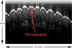
By replacing the light source in a Santec Corp. (Komaki, Japan) Inner Vision OCT system with our dispersion-tuned wavelength-swept fiber laser, we were able to perform SS-OCT imaging.5 An image of the human finger at a 1 kHz sweep rate does show a stripe pattern near that surface that derives from system noise (see Fig. 4). With a resolution of 16 µm and a sensitivity of about 87 dB, the depth at which the signal has a 6 dB drop-off is 0.38 mm. Although this depth range is not sufficient for OCT imaging, the sweat gland under the surface of the finger can be observed near the center of the image.At sweep rates greater than 100 kHz for this initial SS-OCT system, the laser output power decreases and the instantaneous linewidth broadens mainly because the laser cavity length is too long and the wavelength is shifted before the light perfectly oscillates at higher sweep speed. In order to shorten the laser cavity and solve this problem, we replaced the 100 m DCF with a chirped fiber Bragg grating (CFBG). The cavity length is reduced by a factor of ten and performance is dramatically improved. Furthermore, we tried a reflective SOA (RSOA) as the gain medium and made a linear cavity instead of the existing ring cavity. The laser length in this case was approximately 2 m and performance was further improved.
Using the CFBG configuration, we successfully obtained OCT images of adhesive tape at 50 kHz, clearly identifying several layers of the tape. Additional images at a 125 kHz sweep rate—although with more limited depth range than the 50 kHz images—clearly indicate the potential of filter-free, dispersion-tuned fiber lasers as real-time OCT imaging sources.
REFERENCES
1. R. Huber, M. Wojtkowski, and J.G. Fujimoto, Opt. Exp., 14, 8, 3225–3237 (April 2006).
2. D. Huang et al., Science, 254, 5035, 1178–1181 (November 1991).
3. S. Yamashita and M. Asano, Opt. Exp., 14, 20, 9299–9306 (October 2006).
4. Y. Nakazaki and S. Yamashita, Opt. Exp., 17, 10, 8310–8318 (May 2009).
5. Y. Takubo and S. Yamashita, IEEE Photon. Technol. Lett., 24, 12, 979–981 (June 2012).
Yuya Takubo is a master’s degree student and Shinji Yamashita is a professor in the Department of Electronic Engineering, University of Tokyo, 7-3-1 Hongo, Bunkyo-ku, Tokyo 113-8656, Japan; e-mail: [email protected]; www.u-tokyo.ac.jp.


