INTERFEROMETRY: Speckle interferometer detects position at high speed
Anyone working with visible-light lasers can’t fail to notice the speckle patterns that coherent light produces upon reflection from a scattering surface. Moving either the point of view or the surface itself causes the speckle patterns to appear to slide one way or the other. By merely noticing this pattern, one is performing a simple type of speckle interferometry.
In the conventional instrumentation form of speckle interferometry, the speckle pattern from a diffusely transmitting or reflecting surface is monitored by an imaging detector; movements in the pattern provide information on in-plane (lateral) translation of the surface. However, because this technique (which has been around for almost as long as the laser) relies on imaging detectors, it is far slower than, for example, distance-measuring laser interferometry, which measures the longitudinal displacement of a mirror using a nonimaging photodetector (which can be a high-speed photodiode).
Now, Dutch researchers from the University of Twente (Enschede), the FOM Institute for Atomic and Molecular Physics (Amsterdam), and Philips Research Laboratories (Eindhoven) have created a nonimaging speckle interferometer that uses a photodiode to detect the lateral position of a scattering material at high speed over a small range to nanometer precision.1 The technique relies on a wavefront synthesizer to create a sharp focus from the scattered light reflected from the surface.
Wavefront fingerprint
The synthesizer is a spatial light modulator (SLM) with 1024 × 768 pixels from Holoeye Photonics AG (Berlin-Adlershof, Germany) based on a reflective liquid-crystal-on-silicon (LCOS) microdisplay. The beam from a green (532 nm) continuous-wave laser passes through the wavefront synthesizer and is then transmitted through the diffuse surface; via a feedback algorithm using the output from a small photodiode, the laser beam—and thus the returning wavefront—is optimized by the SLM to produce a focus, resulting in a wavefront “fingerprint.” Using a second photodiode in a different position, another spatially separate substrate position is calibrated this way, producing a second wavefront fingerprint. (Other translational directions can be measured by creating additional fingerprints combined with additional detectors.)
If the sample is then placed in a position somewhere between the two calibrated positions, its position can be determined by illuminating the surface with a wavefront that is constructed by coherently summing complex amplitudes of the two wavefront fingerprints, measuring the intensities at the two detectors, and interpolating from the intensity difference. The sensitivity of the technique depends on the illumination optics, which determine the scale of the speckle pattern.
A sample was constructed of zinc oxide powder on a glass cover slide. For experimental purposes, a CCD camera was placed at the far field of the transmitted and scattered output; however, the camera typically would be replaced by two photodiodes for high-bandwidth use.
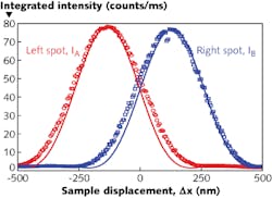
For the particular experimental setup, the researchers created wavefront fingerprints for sample positions in the x-axis of -126 and +126 nm, producing a single sharp focus for each at different positions on the camera. Moving the sample to x = 0 nm produced two spots of similar intensity; a shift to +60 nm reduced the intensity of one spot and increased the intensity of the other without changing the positions of the spots. The two spot intensities were measured as a function of sample displacement (see figure).
Near x = 0, the intensity difference between the two detectors is an approximately linear function of displacement. The experimental sensitivity at x = 0 was 0.66 counts/ms/mm. The noise level was measured to be 1.42 counts/ms, resulting in a displacement resolution of 2.1 nm. Because part of the “noise” in the experiment could actually be fluctuations in sample position (which is signal, not noise), the true noise level may be lower.
The researchers note that their technique could be used for reflective samples, to detect displacement along more than one direction, and, if modified, to measure sample rotations.
REFERENCE
1 E.G. van Putten et al., Opt. Lett., 37, 8, 1070 (Mar. 15, 2012).
About the Author

John Wallace
Senior Technical Editor (1998-2022)
John Wallace was with Laser Focus World for nearly 25 years, retiring in late June 2022. He obtained a bachelor's degree in mechanical engineering and physics at Rutgers University and a master's in optical engineering at the University of Rochester. Before becoming an editor, John worked as an engineer at RCA, Exxon, Eastman Kodak, and GCA Corporation.