MICROSTRUCTURED FIBERS: Air-core microstructured fibers provide low-loss, broadband terahertz guidance
JESSIENTA ANTHONY, RAINER LEONHARDT, SERGIO LEON-SAVAL, and ALEXANDER ARGYROS
Guiding terahertz radiation in waveguides continues to be one of the most engaging research areas in terahertz science. The lack of highly transparent materials in the terahertz band motivates the search for desirable waveguides that not only offer lossless terahertz propagation, but also low dispersion and highly flexible terahertz waveguiding. Conventional waveguides such as terahertz fibers made of sapphire and polymer tubes, as well as metallic-based wires and plates, have been intensely investigated over the years.1
In contrast, a new class of terahertz waveguides draws on the knowledge and the technology of photonic-crystal fibers (PCFs) developed for the visible to mid-IR spectral regions for use in the terahertz frequency range.2 Of particular interest are hollow-core PCFs that allow light guidance in the air core, providing a promising platform for lossless transmission with very low dispersion. We recently demonstrated terahertz guidance in air-core "kagome" poly-methylmethacrylate (PMMA) PCFs with measured propagation losses reduced by 20 times compared to the material losses, and also achieved low dispersion over a broad transmission region.3 ("Kagome" refers to the pattern used in the PCF, which looks similar to a trihexagonal tiling.)
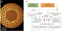
The kagome fiber that we investigated is drawn from a preform that is made by stacking PMMA tubes in a triangular lattice with the core formed by removing seven tubes from the stack (see Fig. 1). The drawn fibers have core diameters of 1.6 mm (Kagome-1) and 2.2 mm (Kagome-2), with outer diameters of 5 mm and 6.8 mm, respectively.
Standard measurement techniques employing a terahertz time-domain spectroscopy setup are used to evaluate these fiber samples. In this setup, light pulses with an 800 nm wavelength and a pulse duration of 80 fs from a Ti:sapphire laser are split into two arms: a pump beam that impinges on a surface emitter and generates terahertz pulses via optical rectification, and a probe beam that optically gates a photoconductive antenna detector. This detector directly maps the terahertz electric field that arrives at the antenna as a function of the delay time between the pump and the probe beams. For good mode matching and thus high coupling efficiencies, we incorporated specially designed symmetric-pass terahertz lenses with a focal length of 75 mm and a numerical aperture of 0.33.4
Performance of terahertz kagome fibers
The underlying guiding mechanism of the kagome fibers does not rely on a photonic bandgap (an absence of photonic states in the cladding structure) to confine light in the core, but relies on an inhibited coupling mechanism instead, in which there is a reduced interaction between the core-guided modes and the cladding modes.5,6 The latter modes originate from the modes that are supported by the dielectric struts in the cladding. Strong power coupling between the modes occurs when they are at resonance. At nonresonant frequencies, however, the minimized physical overlap between the core and the cladding modes allow the core mode to remain propagating with low leakage (low loss).
By computing and comparing the Fourier transforms of the temporal signals with and without the fibers, we can extract the attenuation coefficient and the phase index of the guided mode in the fibers. Power-attenuation coefficients for the fibers, averaged over several lengths, can be seen in Fig. 2. The spectra show distinct loss peaks at certain frequencies, which we have identified as the resonant frequency (highlighted as a gray area in the figures) of the cladding mode.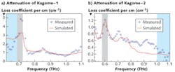
Experimentally, at the resonant frequency we observed that the fundamental mode leaks into the cladding regions without vanishing. In the transmission windows, we found loss coefficients of about 1 cm-1 (4.3 dB cm-1) between 0.75 and 1.1 THz for Kagome-1 and less than 0.6 cm-1 (2.6 dB cm-1) in the 0.65–1.0 THz range for Kagome-2. The agreement with simulation results calculated using a finite-difference frequency-domain method is exceptional for Kagome-1 and still quite good for the Kagome-2 data. From these measurements, we estimate coupling efficiencies as high as 60% can be achieved with our lenses.
Lower losses in larger fiber
Comparing the data of the two fibers, the 38% lower losses achieved by the Kagome-2 are due to the larger core size of the fiber. The extent of the spatial overlap of the modes in the larger-core fiber is diminished due to the greater distance of the cladding walls from the center of the mode in the core. The core is sufficiently large to make the material absorption negligible, which also eliminates the need for using lower-loss materials. This is supported by simulations of an identical structure to Kagome-2, where we reduced the fiber material losses by 60 times in comparison to that of the PMMA, yet the loss figure obtained from this simulation was approximately the same as for the PMMA fiber.
Figure 3 shows the phase index of the fiber modes calculated from the extracted phase details and adjusted for the 2π phase ambiguity. In the resonance regimes (highlighted gray areas) we see that the rapid changes in the phase index of the modes do not originate from the noise of the data, but are the signatures of the limit of the phase mismatch or the avoided crossing between the core and the cladding modes. Outside the high-loss regions, the core mode propagates with an effective phase index close to that of air, showing good agreement with the simulation results.
For broadband pulse systems, it is important to evaluate the group-velocity dispersion (GVD) of the pulses propagating through the kagome fibers. The GVD parameter is the measure of the pulse spreading over the distance traveled and is analytically expressed as ∂2β/∂ω2, where β is the propagation constant related to nω/c (n is the effective mode phase refractive index; ω is the angular frequency; and c is the speed of light).
As shown in Fig. 3, the GVD parameter evaluated from the experiments conforms to the pattern exhibited by the GVD values obtained from simulations in the range where the signal-to-noise ratio is large. The larger fluctuations in the data points, especially at higher frequencies, are caused by the amplification of the noise as a result of differentiating the function of the phase index twice. Overall, both of the kagome fiber GVD simulation results show they can achieve very low dispersion over a wide spectral band, comparable to what can be achieved, for instance, in a solid-core PCF.7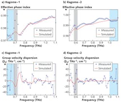
These low-loss, low-dispersion kagome terahertz fibers may find niches not only in broadband terahertz guidance, but also in terahertz-sensitive sensing of thin films deposited in the fiber structure and studies of terahertz light-matter interaction with gases and plasmas inside the fiber core.
REFERENCES
1. K. Wang and D. M. Mittleman, Nature, 432, 7015, 376 (2004).
2. P. Russell, Science, 299, 5605, 358 (2003).
3. J. Anthony et al., Opt. Exp., 19, 19, 18470 (2011).
4. Y. H. Lo and R. Leonhardt, Opt. Exp., 16, 20, 5991 (2008).
5. F. Couny et al., Science, 318, 5853, 1118 (2007).
6. A. Argyros et al., Opt. Exp., 15, 12, 7713 (2007).
7. J. Anthony et al., JOSA B, 28, 5, 1013 (2011).
Jessienta Anthony and Rainer Leonhardt are at the Department of Physics, University of Auckland, Private Bag 92019, Auckland, New Zealand; e-mail [email protected]. Sergio Leon-Saval and Alexander Argyros are at the Institute of Photonics and Optical Science (IPOS), School of Physics, University of Sydney, Sydney NSW 2006, Australia.