ASTRONOMICAL IMAGING: New adaptive optics system at Lick Observatory uses MEMS
DONALD GAVEL
Astronomers have a limitation when using telescopes on Earth: The air turbulence distorts and blurs the incoming light. Spaceborne telescopes overcome this limitation, but they are limited in terms of the collecting aperture by the size, weight, and cost considerations associated with launching to space. The largest space observatory, the Hubble Space Telescope, has a 2.6-m-diameter primary mirror, which is relatively small compared to the several ground-based observatories with 8- and 10-m-aperture telescopes, and the 30–40 m telescopes currently being planned. Almost all the big ground-based observatories today use adaptive optics systems and instruments dedicated to high-resolution science imaging. Adaptive optics is a means of correcting for the atmospheric turbulence during an exposure, enabling astronomers to take advantage of the diffraction-limited resolution of the large aperture.
As apertures and demands for better resolution increase, the technology for adaptive optics (AO) components is also evolving. The heart of an AO system is its deformable mirror, the element that actually corrects for the wavefront distortions introduced by the atmosphere. The wavefront distortion is a complicated, random, and rapidly varying shape that the deformable mirror must match dynamically in order to correct it. The deformable mirror is traditionally a thin piece of glass coated with a reflective surface (usually silver, aluminum, or gold for astronomy) and having a number of controlled piston elements pushing on the back of the glass. Properly controlled, these actuators force the correct shape on the glass and its reflecting surface. The technology challenge going forward is to scale up the number of control elements for larger aperture and shorter science wavelength application, while keeping the device small and reasonable in cost.
MEMS deformable mirrors
Micro-sized technologies, or microelectromechanical systems (MEMS), have been developed for several application areas including microfluidic control, microtransducers, biology sampling, and optics. These MEMS devices perform functions traditionally done by machines, such as a gear or a pump, but scaled down to sub-millimeter sizes. The MEMS device manufacturing is often done using basically the same microfabrication technology developed for integrated circuit fabrication. The MEMS are built up by depositing layers of material (silicon, glass, or metals) and selectively removing material by etching to produce a three-dimensional structure that can move, typically in response to an applied voltage.
Deformable MEMS mirrors have a base with electrodes, a gap area, a conductive membrane, and a surface layer on which reflective metal is coated, along with all the supporting structures (see Fig. 1). Devices constructed by Boston Micromachines Corp. (Boston, MA) have been incorporated into AO systems at Lick Observatory. Several other MEMS manufacturers are also coming up to speed in meeting the challenges of astronomical AO. Boston Micromachines has marketed a 1024-actuator device and recently produced a 4096-actuator device under contract.
For astronomy AO, the MEMS must move into position several hundred times per second to the precision of a fraction of the wavelength. This is done over a surface that is mapped optically onto the primary aperture of the telescope. Since the atmosphere’s coherence length at the ground is only a few tens of centimeters at visible wavelengths, this means the deformable mirror must have many degrees of motion across its surface—on the order of 10,000 for a 30 m aperture.
Adaptive optics at Lick Observatory
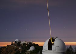
Lick Observatory (Mount Hamilton, CA) has been used for forefront research in astronomy for more than 100 years. The Shane 3 m telescope was one of the first to implement AO and was a pioneer in developing the laser-guidestar-based AO systems now used at several observatories worldwide (see Fig. 2).1 Being in close proximity to several University of California campuses, the observatory functions as a research hub and hosts pathfinder experiments for technology development. The AO system, installed in 1994, was a prototype for the later systems installed at the Keck 10 m telescopes in Hawaii (of which UC is a partner).2In 2007 we implemented a testbed system on the 1 m Nickel telescope to do our first atmospheric correction experiments using a MEMS deformable mirror.3,4
Today, a new AO system for the Shane 3 m is under development, which incorporates many of the significant advances in AO device technologies that have taken place over the past decade, in particular MEMS deformable mirrors. This new system will advance upon the older one by improving the AO system performance and by extending the science reach to shorter-wavelength astronomical bands.
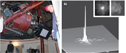
The MEMS device to be used on the Shane telescope has a 32 × 32 array of actuators, each capable of deflecting the reflective mirror surface by about 3 μm. The actuator grid is mapped to the telescope aperture (3 m in diameter) so that the incoming waves are corrected on scales of 10 cm, which is fine enough to coherently re-phase the atmospherically distorted starlight to wavelengths as short as mid-visible (λ = 0.5 μm). To correct a star image in the 1 m telescope’s test system, light ordinarily scattered over about 1 s of arc on the image is gathered into about 0.1 arc-second (the diffraction-limit of the 1 m telescope), making the image both sharper and brighter with respect to the background (see Fig. 3). In the 3 m AO system, the diffraction limit is three times sharper and the contrast is expected to be nine times brighter.With this degree of high-precision correction in the new AO system, we will have extraordinary correction of the J, H, and K astronomical near-infrared (NIR) wavelength bands (mapped to transmission bands of the atmosphere near 1.2, 1.6, and 2.0 μm respectively), and have some correction of “visible” bands at shorter wavelengths from 0.5 to 1.0 μm. Compared to the previous system, which only usefully AO corrects the K band, we are opening up immensely useful multicolor observations and bringing into play key shorter-wavelength emission lines such as the calcium lines at λ = 0.8542 and 0.8662 µm, which are useful for star formation and galaxy evolution studies.
Using the latest in silicon MEMS technology, along with developments in other key areas such as high-speed low-noise detectors for wavefront sensing, lasers to produce the artificial guidestars, and more sensitive IR science detector arrays, the Shane AO system will provide a modern platform for high-resolution astronomy. In addition to expanding the science capabilities at Lick, the system will be a demonstration pathfinder for next-generation systems on the world’s largest telescopes.
ACKNOWLEDGMENTS
We gratefully acknowledge support from the National Science Foundation, Astronomical Sciences Division, through a Major Research Instrumentation grant. Matching support for this project is being provided by the University of California Lick Observatory.
REFERENCES
1. C.E. Max et al., “Image Improvement from a Sodium-Layer Laser Guide Star Adaptive Optics System,” Science, 277, 5332, 1649–1652 (1997); doi:10.1126/science.277.5332.1649.
2. P. Wizinowich et al., “First Light Adaptive Optics Images from the Keck II Telescope: A New Era of High Angular Resolution Imagery,” Publications of the Astron. Soc. of the Pacific, 112, 769, 315–319 (2000); doi:10.1086/316543.
3. S.A. Cornelissen, A.L. Hartzell, J.B. Stewart, T.G. Bifano, and P.A. Bierden, “MEMS deformable mirrors for astronomical adaptive optics,” Proc. SPIE, 7736 (2010); doi:10.1117/12.857296
4. D.T. Gavel, “Progress update on the visible light laser guidestar experiments at Lick Observatory,” Proc. SPIE, 7595 (2010); doi:10.1117/12.846773.
Donald Gavel is director of the Laboratory for Adaptive Optics at UCO/Lick Observatory, University of California, Santa Cruz, 1156 High St., CfAO Building, Santa Cruz, CA; e-mail: [email protected]; http://lao.ucolick.org.


