INTERFEROMETRY: Emerging applications push receivers to higher speeds
OVIDIO ANTON
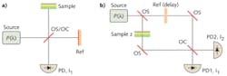
Optical interferometric measurements are customarily implemented by splitting a light beam into two paths that are subsequently recombined to interfere on one or more photosensitive devices. Generally one of the optical paths serves as a reference beam and other path serves as a sample beam that interrogates the object of interest. The interferometric signal results from the coherent superposition of the two optical beams. Practical examples of two-path interferometers include Michelson and Mach-Zehnder configurations (see Fig. 1).
In a Michelson interferometer where sample and reference beams are split and recombined by the same beamsplitter, the photodiode current I1 is proportional to the power envelope of the sum of the combined beam electric fields, which to first order approximation is given by:
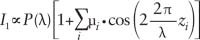
where zi and µi are the optical distance and reflection amplitude from the ith reflecting interface.
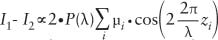
For the Mach-Zehnder interferometer, the sample and reference paths are recombined into a second optical combiner after passing through the reference delay and sample material. The first photocurrent I1 is similar to that in the Michelson interferometer, whereas I2 is approximated by:
It is fundamental to coherent detection that the useful detected photocurrent signal is proportional to both the sample power µ · P(λ) and the reference power P(λ) and so is given by:
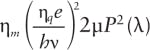
The photodiode shot noise is given by:
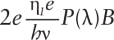
where e, B, ηq, ηm, and hν are the electron charge, electrical bandwidth, quantum and heterodyne efficiencies, and photon energy, respectively. There is therefore a limit to the signal-to-noise-ratio (SNR) of
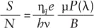
for single photodiode detection. When using a laser with significant relative intensity noise (RIN), the SNR will be reduced from this level.
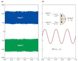
A practical method to approach the shot noise limit in the presence of RIN or other common-mode noise sources relies on utilizing and mutually subtracting the two photocurrents I1 and I2 using balanced detection.1 In the case of a perfect 50/50 optical combiner, the balanced photoreceiver output completely rejects the common-mode power:
Balanced photoreceivers are available from many vendors with a wide variety of bandwidths and sensitivity, some featuring adjustable gain. Signal subtraction can also be accomplished after both signals are digitized but directly subtracting the two signals with analog circuitry avoids any issues with sampling errors and can be significantly more sensitive.
Autobalanced photoreceivers
The crucial challenge to optimizing balanced detection is in achieving the ideal power balance between the two signals. Though the power ratio in each beam is given by geometry and polarization, these can easily vary with thermal drift or wavelength dependence. Any imbalance between the photocurrents generated by the reference and signal photodiode, whether intentional or otherwise, results in a degraded common-mode rejection ratio (CMRR). To eliminate the problems associated with manually balancing the reference and signal beams, it is possible to design an autobalanced photoreceiver with a built-in low-frequency feedback loop that controls the electronic gain of one of the receivers and maintains automatic balance between signal and reference arms.
We developed the “Nirvana” autobalanced receiver based on Hobbs’ work at IBM.2 It incorporates two photodiodes (one each for the signal and reference beams), a current splitter, a current subtraction node, a transresistance amplifier, and a feedback amplifier. A low-frequency feedback loop maintains automatic DC balance between the signal and reference detector arms. This photoreceiver can deliver low noise and exceed a 45 dB rejection to source noise (CMRR) at frequencies below 125 kHz in dynamically changing balance conditions.
However, there are some applications—such as high-speed optical coherence tomography (OCT)—that require balanced photoreceivers with bandwidths of more than 100 MHz. To address these applications we have developed the GHz Nirvana photoreceiver, which is based on two high-speed indium gallium arsenide fiber-coupled photodiodes and operates at wavelengths from 900 to 1650 nm. Its high-speed telecom receiver core balancing circuit generates a balance control voltage from signals in the range from 30 kHz to 1 MHz.3 The relative gain of the two photodiodes is then automatically controlled to effectively reject common-mode noise at frequencies up to 1 GHz.
OCT with autobalanced detection
Optical coherence tomography is an application that benefits significantly from high-speed balanced detection and is showing strong commercial growth.
The performance of swept-source OCT (SS-OCT) systems can be improved by both balanced and autobalanced detection (see Fig. 3). Balanced detection OCT allows the subtraction of all common-mode noise and improves the ability to resolve low scattering features deep in the sample. Manually balanced and autobalanced modes can produce similar results for slow changes in split ratio, but the autobalanced mode enables measurement systems that can accommodate drift over time. It also eliminates the need to make an initial adjustment (either optical or electrical) to achieve good balance. Both of these benefits make the receiver well suited for use in commercial systems where ease of assembly and solid performance over both temperature and time are important.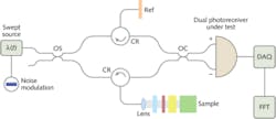
Another important consideration for any photoreceiver in a swept-wavelength system is etalon-free optical delivery to the photodiode. Reflections off the lens used to focus onto the small photodiode can introduce interference, which results in a wavelength-dependent ripple leading to unacceptable artifacts in the resultant OCT image. The gigahertz Nirvana receiver was carefully designed to achieve artifact-free performance.
To demonstrate the benefits of a high-bandwidth autobalanced receiver we tested a SS-OCT system using a New Focus model 8700 laser, which sweeps in wavelength and was also directly modulated to present a large source noise as common-mode input to the receiver. Multiple plastic laminates and a final reflection on a business card were placed in the sample arm (see Fig. 4).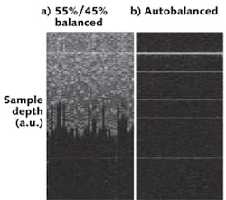
Outlook
The autobalancing feature and high bandwidth make this high-speed receiver well suited for use in emerging applications such as fast SS-OCT. Although existing SS-OCT requires a photoreceiver with a bandwidth greater than 100 MHz, we believe increasingly faster laser sweep and data acquisition rates will require balanced photoreceivers with bandwidths approaching 1 GHz in the near future.
REFERENCES
1. H.R. Carleton et al., “A balanced optical heterodyne detector,” Appl. Opt., 7, 6, 1241 (1968).
2. P. Hobbs, US Patent 5,134, 276.
3. Newport patent pending.
Ovidio Anton is a senior optical engineer at the New Focus division of Newport Corp., 1791 Deere Ave., Irvine, CA 92606; e-mail: [email protected]; www.newport.com.