CAVITY-RINGDOWN SPECTROSCOPY: ICOS isotope-ratio measurement sheds new light on climate change
The dramatic decrease in Arctic sea ice in the summer of 2007 was not predicted, and according to some scientists, not well characterized in scientific models.1Quantitative analysis of gases such as methane and carbon dioxide being released from warming permafrost and oceans is necessary to determine the net carbon loading to the atmosphere; however, the rate at which methane is being released and the source and age of the organic matter that decays to create methane is uncertain.
Because existing remote-sensing and flux models have fallen short of providing accurate spatial and temporal gas measurements over the vast Arctic region, and because it is estimated that, in addition to the 8 gigatons (Gt) of atmospheric carbon released per year due to human activity, as many as 2000 Gt are contained in Arctic soils and oceans, scientists at Harvard University (Cambridge, MA) are proposing that a spectroscopic isotope-ratio measurement be used to provide more accurate carbon measurements and to lay the foundation for a national carbon-monitoring network.2
The ICOS method
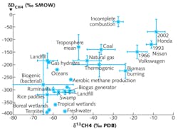
A carbon instrument using both an off-axis integrated-cavity-output spectroscopy (ICOS) technique and a spherical Herriott cell developed at Harvard University can achieve simultaneous measurements of the stable isotopes of methane (12CH4, 13CH4) and carbon dioxide (12CO2, 13CO2, 12CO18O).3 These isotopes can be used to compute the ratio of carbon 13 (13C) to carbon 12 (12C), denoted as δC13. This δC13 value is different for man-made combustion of thermogenic sources of carbon (such as natural gas and coal) versus natural biogenic sources (such as wetlands, animals, and bacterial emissions), and can be measured by ICOS with a precision of 1.0‰ (per mil or parts per thousand) in 1 s or 0.1‰ in 200 s—a precision (better than 1.0‰) needed to accurately identify the source of atmospheric carbon (see figure).
The breakthrough sensitivity and time response of the ICOS method are made possible by the factor-of-10-to-100 path-length increase for this system, enabling carbon-isotope measurements from a flying aircraft. The ICOS instrument has a high-finesse optical cavity composed of two high-reflectivity (99.967%) zinc-selenide mirrors (10 cm diameter with 140 mm radius of curvature) that trap the light from a 7.7 µm continuous-wave quantum-cascade laser from Hamamatsu Photonics (Bridgewater, NJ) for a period on the order of 1 to 10 µs, resulting in effective path lengths 1,000 times as large as the 50 cm mirror separation. The laser scans across the spectral absorption feature(s) of interest as ambient air is pulled in from special aircraft inlets, and the intensity of the light in the cavity is measured. Changes in intensity are due to absorption and loss of light through the two cavity mirrors. In this ICOS variation of cavity-ringdown spectroscopy (CRDS), the laser is aimed “off-axis” to minimize spontaneous interferences that can mask spectral features of interest.
In addition to the isotope-ratio measurement for methane, the scientists also developed spectrometers to measure carbon-dioxide isotopes. The carbon instrument is combined with the best-air-turbulence (BAT) probe developed by NOAA to measure not just the concentration of gases but the flux of those gases being emitted from the surface.
“We’re excited to be working with NOAA and Aurora Flight Sciences—who will be operating the aircraft—to make these measurements,” says David Sayres, a research associate in professor James Anderson’s group at Harvard. “Methane and carbon dioxide released from melting Arctic permafrost has the potential to greatly amplify carbon loading in the atmosphere due to anthropogenic emissions. It is imperative to understand the magnitude and cause of this release as it will have a profound effect on both the climate and policy decisions concerning the timing and magnitude of fossil-fuel use reduction. Our first flights will begin late summer 2011 in the North Slope of Alaska, and will continue in subsequent years in the spring, summer, and fall. The approach we are using can also be a first step in monitoring carbon emissions in the US and abroad, a necessary part of any practical carbon-emissions treaty.”
REFERENCES
1. J. Boe et al., Nature Geoscience, 2, 341 (2010).
2. D.S. Sayres et al., “Multi-Regional Scale Aircraft Observations of Methane and Carbon Dioxide Isotopic Fluxes in the Arctic,” proposal for consideration to NSF (March 2011).
3. M.F. Witinski et al., Appl. Phys. B, 102, 375 (March 2010).
About the Author

Gail Overton
Gail Overton served as a senior editor for Laser Focus World from 2004 through 2020. She has more than 30 years of engineering, marketing, product management, and editorial experience in the photonics and optical communications industry. Before joining the staff at Laser Focus World, she held many product management and product marketing roles in the fiber-optics industry, most notably at Hughes (El Segundo, CA), GTE Labs (Waltham, MA), Corning (Corning, NY), Photon Kinetics (Beaverton, OR), and Newport Corporation (Irvine, CA). During her marketing career, Gail published articles in WDM Solutions and Sensors magazine and traveled internationally to conduct product and sales training. Gail received her BS degree in physics, with an emphasis in optics, from San Diego State University in San Diego, CA in May 1986.