MULTISPECTRAL/HYPERSPECTRAL IMAGING: CMOS takes hyperspectral imaging beyond the laboratory
ANDY LAMBRECHTS, KLAAS TACK, and FRANCESCO PESSOLANO
As an emerging technology in the machine-vision domain, hyperspectral imaging is expected to benefit numerous applications, ranging in the short term from optical sorting and recycling to miniature hyperspectral cameras for in vivo cancer diagnosis in the long term, for example. Although the potential of hyperspectral imaging has been demonstrated for several applications using laboratory setups, it is still largely a laboratory tool. Its adoption by industry has been limited due to the lack of fast, compact, and cost-effective hyperspectral cameras with adequate specifications for industrial-strength image processing. To enable the transfer of applications from the lab to industry, some hurdles must be overcome.
A new spectral concept
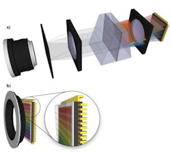
Several research communities, including Belgian research center Imec, are seeking solutions to build a better, faster, more economical hyperspectral camera that eliminates many of the expensive and bulky optical components of current systems. To achieve these challenging goals, Imec researchers developed an integrated hyperspectral imaging module that is used as a scanner, meaning that objects are mechanically translated with respect to the imager in order to capture a full hyperspectral image (see Fig. 1).
Because a hyperspectral image cube is a three-dimensional (3D) dataset (two spatial dimensions and one spectral dimension), it has to be split up in order to be captured by a two-dimensional (2D) sensor. Existing cameras often use a linescanning technique that captures a single line of the scene of interest at different wavelengths in parallel. Other techniques capture the complete scene at a single wavelength—in this case, a sequential scanning of different wavelengths of interest is then needed; however, this sequential scanning slows down the system speed. Our hyperspectral module can be used in mixed spatial/spectral scanning mode, in which different lines of the scene are captured in parallel at different wavelengths. This means that as a result of the scanning movement, over time, every line will be captured by every spectral filter on the module.
In addition to this novel scanning process, optical filters are monolithically integrated with our complementary metal-oxide semiconductor (CMOS)-based hyperspectral image sensor; that is, the optical filter is directly processed on top of the image sensor (see Fig. 2). In order to make this tight integration possible, the filter structure designs must make use of advanced techniques developed for integrated circuit (IC) production and consequently have to work with materials and temperatures that will not compromise the functionality of the image sensor on which they are processed. In practice, this is a material selection (dependent on the required wavelength range) and material compatibility exercise. A series of process development steps including planarization, surface conditioning, and refractive-index engineering must be performed in order to achieve the required dimensions and the related optical performance and reliability.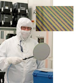
Combining the image sensor and hyperspectral filter structure leads to simplified designs and lower cost when compared to hybrid systems in which optical elements (prisms, gratings, lenses) are separately produced and later packaged with the image sensor and hyperspectral element. As the alignment of all elements in a hybrid system is essential to system performance, the integration and calibration steps can be costly. When the different components of the hyperspectral element are monolithically integrated, a single component is produced that does not require further assembly. Our filter structures have been designed to require only CMOS-compatible fabrication steps such as deposition, patterning, and etching. By adding these steps to the normal production flow of the image sensor, expensive, error-prone, and labor-intensive assembly steps are prevented. The extreme process control and accuracy of IC production steps enables a very accurate and repeatable alignment of both components, while the integrated flow drastically reduces the overall cost.
By post-processing the filter structure directly on top of the pixels of the imager, photons pass directly from the filter into the pixel below. When the filter structure is produced separately and stacked on top of the image sensor, there will always be a non-functional layer or gap in between both structures. This extra layer between the filter structure and the underlying rows of pixels gives rise to a certain amount of performance degradation, including coupling losses or parasitic filter effects due to a large number of carrier layers. The main advantage of monolithic integration and thin-filter design on imager performance and efficiency, therefore, is reduced crosstalk due to thinner filters, creating less stray light and internal reflections that could negatively affect spectral and spatial resolution (see Fig. 3).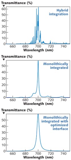
The filters will have a certain filter width with a defined full-width half-maximum (FWHM) and the spectral range will be sampled by spacing different filters with respect to each other. The design can be made tolerant to process variation by introducing extra filters, by oversampling, and by overlap.
Specifically, the introduction of extra filters that sample the spectrum at both sides, just outside of the targeted spectral range, can make the design tolerant for a processing error that would shift the complete range of filters up or down. Oversampling is achieved by designing more (partly overlapping) filters than would minimally be required by the application, such that the filter that best matches the required wavelength can be selected even when small processing tolerances have moved the exact location of the filters. In some cases, one or more spectral filters can be duplicated on the module to introduce some form of overlap in the sampling in order to recover from other types of processing tolerances. As different processing steps are sensitive to very different types of tolerances, an accurate analysis of the design will predict how much, at what locations in the spectrum, and what exactly the potential effect is on the filter characteristics. This approach leads to a manufacturable module, without introducing too much overhead.
Another important advantage of the filter structures is reduced sensitivity of the filtered wavelength to the angle of incidence of the light that enters the filters. This reduced sensitivity enables a hyperspectral system design in which more light is allowed to enter the system and in turn enables faster imaging up to 10,000 lines per second instead of the typical 100 lines per second for current systems.
Finally, there is no need for a focusing lens because the filters are directly integrated on top of the image-sensor pixels. In a traditional diffractive-optics-based linescanner, the image is captured by the objective lens and a single line is selected by the entrance slit. The energy of that single line is then collimated. At the output of the collimator, different parallel copies of this single line fall onto a grating, which splits the light into its different spectral components. The focusing lens then focuses all light of the same wavelength onto the same row of pixels of the imager. In Imec’s proposed system, the objective lens projects an image of the full scene directly onto the hyperspectral imaging module. In the module itself, extremely thin filters select the wavelength of interest directly on top of the different rows of pixels.
Tuning in to applications
Because hyperspectral imaging is applicable to many industries, the requirements of targeted applications vary greatly, allowing tradeoffs in speed, spectral resolution, compactness, and cost. Our hyperspectral imaging system can be tuned to the specific requirements of an application domain by the selection (or custom design) of the image sensor and hyperspectral filter structure.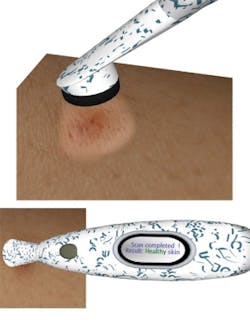
By coupling the application requirements directly to the design of the system and the hyperspectral module, domain-specific instances can be designed that achieve the correct tradeoff point and are directly usable in the industrial or medical application being targeted. Our current prototype devices have already been applied to food-sorting and recycling applications and smaller and less expensive devices will ultimately benefit such applications as the early detection of skin cancer (see Fig. 4).
Andy Lambrechts and Klaas Tack are NVISION program researchers, and Francesco Pessolano is NVISION program manager at Imec, Kapeldreef 75, B-3001 Leuven, Belgium; e-mail: [email protected]; www.imec.be.