HIGH-POWER OPTICS: Laser-machined pits replace coating flaws
For optics used with high-energy lasers, even small flaws in optical coatings can cause catastrophic damage to the optics: As damage is done to the flaw by the laser, more light is absorbed, causing a runaway effect. As a result, high-peak-power optical coatings for large optics can be very difficult and expensive to make, because only one or a very small number of flaws make the entire optic unusable.
Instead of multiplying expenses by rejecting all but perfect optics, a team of scientists working on mirrors to be used in the National Ignition Facility (NIF; Livermore, CA) has come up with a way to cope with potentially destructive flaws in the multilayer-dielectric reflective coatings.1 First, the defects are identified by subjecting the coating to laser light at a carefully controlled fluence, then each defect is altered so it becomes a benign "mitigation structure" that can exist unchanged even under operational laser-light levels. The alterations can be made using femtosecond laser machining, diamond machining, and/or magnetorheological finishing.2
3D model of intensity
The researchers, who are from Lawrence Livermore National Laboratory (LLNL), the University of California–Berkeley, and Panoramic Technology (also in Berkeley, CA), have modeled and experimentally created mitigation structures that take the form of a round pit with a flat bottom and a conical wall. For the model, commercial finite-difference time-domain software was used to solve Maxwell's equations, providing a 3D map of laser intensity as the beam passes into and reflects from the structure.
The 1064 nm laser wavelength and hafnia/silica multilayer-dielectric structure in the model match the characteristics of large mirrors in the inertial-confinement-fusion research system at NIF. Hafnia has a high refractive index of 1.971, while silica has a low index of 1.4497; the coating on the glass mirror substrate consists of 24 alternating quarter-wave layers of hafnia and silica with a total thickness of about 4 μm.
Calculations were done for many different beam-incidence angles, as well as for both s and p polarizations. Cone angles ranged from 0° to 75° in increments of 15°. For simulations of beams with oblique angles of incidence, the wavelength was shifted to maintain the maximum reflectivity; in addition, effective refractive indices were used instead of the actual values.
The results are presented in terms of electric-field intensification: The value at a certain point is a dimensionless number that is the actual intensity at that point divided by the intensity of the incoming beam. The simulation goes into great detail, producing 3D intensification fields with data that were grouped separately for the two quarter-wave materials.
Reducing intensification
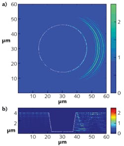
The results show that the relationship between incidence angle, cone angle, polarization, and intensification is quite complicated. For example, for the hafnia layers, a cone angle of 15°, and an incidence angle of 45° from the left, the highest intensification occurs to the right of the pit for s-polarized light (see Fig. 1). However, for p-polarized light and the same geometry, the highest intensification occurs to the left of the pit.
In general, for s-polarized light in the hafnia layers, the maximum intensification ranges from 1.5 to 9.5 depending on the incidence and cone angles. The best way to minimize intensification depends on geometry. For angles of incidence ranging from 0° to 35°, cone angles could range between 0° and 30°, while for angles of incidence greater than 35°, the cone angle could be between 15° and 60° (see Fig. 2).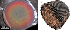
Intensification was lower overall for p-polarized light. For angles of incidence ranging from 0° to 25°, cone angles could range between 0° and 30°. For angles of incidence between 25° and 45°, the best cone angle was between 55° and 65°, while higher angles of incidence benefited from cone angles of between 45° and 75°.
Modeling results for the silica layers were similar to those for the hafnia layers, except for some details: For example, for s-polarized light, 45° irradiation angle, and 15° cone angle, the maximum intensification was seen in a lower layer than that for hafnia.
Further analysis showed that, for all angles of incidence and for cone angles of less than 30°, the primary cause of intensification was a waveguide effect within the layers. It has been hypothesized that one way to reduce intensification would be to have a rough edge at the cone boundary that would break the coherence to reduce waveguiding. However, simulations with a beam angle of incidence of 45°, a cone angle of 15°, and a smooth versus a rough edge, showed little difference. The implication is that the rough edge has a structure too small in relation to the wavelength to have much of an effect.
Repairing real coating flaws
Femtosecond-laser machining was used to create conical mitigation structures with various cone angles on small-aperture optics.3 Experimental results under laser irradiation show that the structures increase a coating's damage threshold by a factor of two. The coatings under test, which are intended for the NIF large-aperture mirrors, have a specified nominal damage threshold of 20 J/cm2; indications for large-area mirrors at NIF are that replacing coating flaws with mitigation structures will raise the damage threshold for the repaired flaws to a level much higher than the mirrors' nominal damage threshold.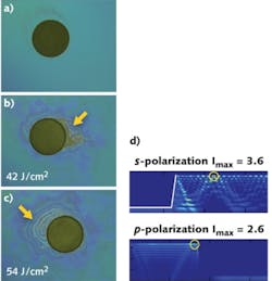
To see what the damage threshold was for experimentally repaired flaws, the researchers raised the laser fluence until damage occurred. For an incidence angle of 45° and a cone angle of 15°, damage occurred at a fluence of 42 J/cm2 for s-polarized light and 54 J/cm2 for p-polarized light. The experimental damage patterns agreed with the simulations (see Fig. 3).
The researchers suggest one of two approaches for practical use. In an overall approach, the cone angle of the mitigation structure could be made equal to the angle of incidence; this works relatively well for a large range of angles. Alternatively, the cone angles could be chosen based on a more-exact fit with the parameters of the model.
"Our next step will be to apply what we learned from the small-aperture optics to full-aperture-sized optics," says S. Roger Qiu, one of the LLNL researchers. "We will further optimize our mitigation process and work to build a robust unit for production purposes."
REFERENCES
1. S. Roger Qiu et al., Appl. Opt., 50, 9, C373 (March 20, 2011).
2. J.E. Wolfe et al., "Laser damage resistant pits in dielectric coatings created by femtosecond laser machining," Proc. SPIE, 7504, 750405 (2009).
3. J.E. Wolfe et al., "Fabrication of mitigation pits for improving laser damage resistance in dielectric mirrors by femtosecond laser machining," submitted to Applied Optics.
About the Author

John Wallace
Senior Technical Editor (1998-2022)
John Wallace was with Laser Focus World for nearly 25 years, retiring in late June 2022. He obtained a bachelor's degree in mechanical engineering and physics at Rutgers University and a master's in optical engineering at the University of Rochester. Before becoming an editor, John worked as an engineer at RCA, Exxon, Eastman Kodak, and GCA Corporation.