POLARIZATION OPTICS: Iridium makes superior wire-grid polarizer for UV

With their large spectral range and conveniently thin platelike form, wire-grid optical polarizers work well in many types of optical systems. At one time only available for the infrared, versions for the visible region have more recently been fabricated. Wire-grid polarizers consist of parallel metallic wires spaced periodically less than a wavelength apart on a substrate (the common Polaroid filters found in polarizing sunglasses and camera filters are of different makeup, consisting of absorbing polymer molecules aligned in one direction). The wire grids get more difficult to fabricate as the desired operating wavelength, and thus the grid spacing, get smaller.
Now, researchers from Friedrich-Schiller-Universität Jena and the Fraunhofer Institut für Angewandte Optik und Feinmechanik (both in Jena, Germany) have created broadband wire-grid polarizers with superior performance in the UV, which at a 300 nm wavelength requires a grid spacing of 100 nm (so that only the zeroth diffraction order is transmitted for all incidence angles).1
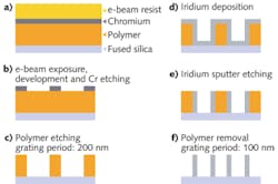
An iridium-wire grid is formed on a fused-silica substrate using a spatial-frequency-doubling technique in which an initial 200 nm grid is processed to form a 100 nm grid. Iridium was chosen over aluminum for a wire material based on the fact that aluminum easily forms an oxide in air that, as the researchers confirmed by a rigorous coupled-wave analysis, reduces the performance of the grating.
Making two features for every one
The substrate is first layered with polymer, a film of chromium, and an electron-beam resist (see figure). An e-beam writer with a lattice aperture is used to create a wire grid with a 200 nm spacing in the chromium film, which then serves as a mask layer for etching the polymer. The resulting 150-nm-high polymer grid, minus the remaining chromium, is deposited with a conformal layer of iridium; the iridium is then subjected to an ion beam that etches away the iridium on top of the ridges and at the bottom of the grooves, leaving metal only on the sidewalls. Finally, the remaining polymer is removed with an oxygen plasma, leaving the frequency-doubled 100 nm grid. For comparison purposes, the researchers also fabricated an aluminum wire-grid polarizer with the same dimensions as the iridium polarizer.
The transmission of TE- and TM-polarized light at wavelengths of 220 to 1200 nm through the gratings was measured with a two-beam spectrometer. At a 300 nm wavelength, for example, the extinction ratios for the iridium and aluminum versions were 30 and 20, respectively, showing the superiority of iridium for the UV (the iridium showed a TM-polarization transmission of about 50% at 300 nm). At a wavelength of about 350 nm, the extinctions were the same, at just above 40; at 500 nm, the extinctions were 60 and 120, respectively, showing that aluminum is a better wire-grid material for the visible region.
REFERENCE
1. T. Weber et al., Opt. Lett., 36, 4, 445 (Feb. 15, 2011).
About the Author
John Wallace
Senior Technical Editor (1998-2022)
John Wallace was with Laser Focus World for nearly 25 years, retiring in late June 2022. He obtained a bachelor's degree in mechanical engineering and physics at Rutgers University and a master's in optical engineering at the University of Rochester. Before becoming an editor, John worked as an engineer at RCA, Exxon, Eastman Kodak, and GCA Corporation.
