LED TEST & MEASUREMENT: Optical testing is an essential aspect of making LEDs
DAN SCHARPF
The explosive growth of light-emitting diodes (LEDs) as a replacement for fluorescent and incandescent light sources is driving tighter requirements on LED performance by the designers of displays and luminaires. Optical testing during the manufacturing process is essential to increase yields and achieve accurate binning, thereby reducing the overall cost of manufacturing. Optical testing now occurs at several steps in the process, starting with wafer probing, followed by testing raw die, taped die, and finally packaged LEDs. Then, after packaging, the LEDS are used in displays and luminaires and these devices also need optical testing. In addition, the end users of the components are often interested in further testing to be sure the light source works well in the intended environment. Due to the sensitivity of LEDs to temperature and installation effects, each stage in the value chain alters LED output and requires testing to validate performance.
In order for LED technology to continue growing and gain industry acceptance the performance and economy of LEDs must exceed that of the components they are replacing. Quantifying the optical performance of an LED device requires measuring intensity (I), flux (φ), color, directivity, and power consumption. Each parameter provides specific information about device performance for a given application and specific testing procedures are provided from the various standards bodies throughout the industry.
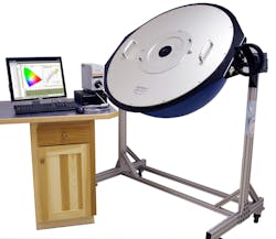
Testing speed during the manufacturing process is essential to maintain production volumes. An integrating sphere in combination with a spectrometer is typically used to capture the total flux along with the spectral content, and hence the color characteristics of the LED. Powering the LED during test also requires special consideration as the pulsed current waveform to the LED is intended to prevent temperature rise in the die yet still produce sufficient and representative light for measurement and qualification. This high-speed process requires precise synchronization between the drive current and the spectrometer.
Binning LEDs
At the initial wafer stage, flux and intensity are required to ensure the desired power and the primary directional properties of the LED. From here, the die is separated from the wafer and again tested for its color characteristics.
At the die stage, the LEDs are sorted based on flux and color criteria—called binning. The process can vary among manufacturers, and recent binning criteria such as NEMA SSL3-2010 are being developed to help standardize the process for the end user. Among the possible binning parameters are radiant flux, dominant wavelength, correlated color temperature, chromaticity, and color rendering index (CRI).
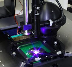
Packaging the LED requires bonding the device die to the silicon and/or heat sink and includes some form of lens to protect the die and provide focusing optics. To create white light, the lens may be coated with a phosphor for diodes that emit short wavelengths. In other white LEDs, a three-die, RGB (red-green-blue) approach is used whereby the color output levels of each die are balanced to produce the white light. In each case, variations in manufacturing processes can yield different color temperatures and color shifts that must be quantified. As before, an integrating sphere is used to bin the packaged devices and provide groups of matched LEDs for specific applications (see Fig. 1).
Light-emitting diodes generally don't fail catastrophically, as do standard incandescent lamps, so the lifetime rating is not easy to predict and there is currently no standard for extrapolating the expected life, or degradation of a LED. Instead, the IESNA-LM-80 standard is used to define the lumen maintenance of the package and define the expected time when the device will produce 70% of its initial light output. Testing at this level requires running a LED for at least 6000 hours at 55°C, 85°C, and a third temperature of the manufacturer's choice. Light measurements are taken every 1000 hours.
Testing luminaires
Luminaire manufacturers must select packaged (binned) LEDs that meet their requirements for a given application. The junction temperature of a LED can significantly impact its optical output power and color shift, which is the reason for the different temperature settings during LM-80 testing. Since the performance of the LED die and package data is provided at 25°C (and 55°C and 85°C if LM-80 data is supplied), the luminaire designer must design the driver and heat management system to optimize the efficacy (flux/input power) or maximize the appropriate optical parameter for the application. This involves simultaneously varying the drive current and controlling the junction temperature at a prescribed value.
An integrating sphere with a thermal controller on the LED package is used to enable the designer to determine the operating envelope in terms of drive current or voltage and junction temperature. With this arrangement, a junction temperature can be fixed for a range of drive currents or vice versa. As this temperature setting is changed, a map of the optical parameters can be created for the complete range of drive current and temperature (see Fig. 2).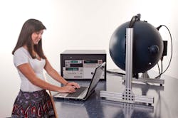
Increased junction temperatures cause reduced light output and shift the dominant wavelength to higher values, resulting in lower correlated color temperatures. Understanding the impact of junction temperature on LED performance allows a designer to determine the acceptable range of operation for the complete luminaire.
Once the optimal operating condition of the LED is determined, the luminaire fixture is designed for performance, form, and aesthetics. Optical testing at this level is again required to verify the output and efficacy of the complete luminaire. Standards such as IESNA-LM-79 provide details on the test methods using an integrating sphere and goniometers so that equivalent comparisons are possible across similar devices.
Since the luminaire housing can impact the thermal management of the LED, LM-79 requires that the solid-state device be tested in the orientation in which it will be used. At this stage in the LED value chain, the housing can be only slightly larger than the LED, or it can be very large, such as in the case of street lamps. Hence testing at this level requires an integrating sphere sized for the housing (see Fig. 3). For testing omnidirectional devices, the luminaire is placed in the center of the sphere (4π arrangement). For directional devices, the luminaire can be directed through a port in the side of the sphere (2π configuration). In each case, the sphere surface area relative to the device area should be maximized. For a 4π configuration the general rule of thumb is that device diameter should be 1/10 the sphere diameter. In the 2π configuration, the sphere port should be less than 1/3 the sphere radius. For street lamps and other large devices, spheres can easily be required to be of 3 m diameter or more.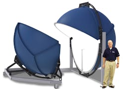
In all of these measurements with integrating spheres, the introduction of the DUT to the sphere alters the ideal spherical configuration upon which integrating sphere theory is based. These additional surfaces change how the light is reflected and absorbed in the sphere and can be corrected through the use of an auxiliary correction lamp. By performing spectrometer scans with the auxiliary lamp illuminated with the calibration lamp and the DUT in position, the ratio of these two scans is used when measuring the output from the DUT and compensates for any reflection or absorption introduced by the DUT.
As described here there are similar requirements for optical testing at every step from wafer to end user. In each step requirements for the integrating sphere and control of the LED vary and must be designed appropriately to achieve measurements within the accuracy range desired.
Dan Scharpf is sales manager in the Systems Business Unit at Labsphere Inc., North Sutton, NH 03260; e-mail: [email protected]; www.labsphere.com.