FLUORESCENCE IMAGING: Nitric oxide PLIF visualizes Mach 10 airflows

Hypersonic air and space vehicles include the Space Shuttle and the US Air Force X-37B, which both re-enter the atmosphere at Mach 25 before slowing to subsonic speeds; and the US Air Force X-51A Waverider scramjet, which flew under its own power for 200 s at Mach 6 earlier this year. One way to test hypersonic airflow phenomena is to use the Mach 10 wind tunnel at NASA's Langley Research Center (Hampton, VA). However, visualizing what happens to a Mach 10 flow of air is not easy, because many things that go on at hypersonic speeds occur at frequencies up to hundreds of kilohertz.
Researchers at Ohio State University (Columbus, OH), Iowa State University (Ames, IA), Johns Hopkins University (Baltimore, MD), and the Langley Research Center have come up with a way to do this nonintrusively, improving the tried-and-true planar laser-induced-fluorescence (PLIF) imaging technique so that their version can image at frame rates up to 1 MHz, rather than the 10 Hz rates of conventional PLIF systems.1
Laser light sheet
In PLIF, light from a pulsed laser is formed into a sheet that illuminates a cross-section of a flowing medium seeded with fluorescent material, with a camera capturing the fluorescence. Because the pulses must be energetic, the lasers have conventionally had low repetition rates. To boost the PLIF frame rate into the 500-kHz-to-1-MHz realm, the research team had to develop a high-repetition-rate laser that could maintain a high pulse energy.
They settled upon a burst-mode laser that creates groups of 10 to 20 pulses at the desired frame rate. The output of a continuous-wave diode-pumped Nd:YAG ring laser oscillator is preamplified in a variable-pulsewidth flashlamp-pumped pulsed amplifier; its output pulse is sliced into a burst train using a dual Pockels cell. Consisting of 20 to 30 pulses each with 10 ns duration and 1 nJ of energy at a 1064 nm wavelength, the burst train is then amplified by six more flashlamp-pumped amplifiers. After amplification, each pulse in the burst train has an energy of about 100 mJ.
Achieving such high pulse energies was a challenge because at high energies, the gain depletion in the amplifier chain after each burst is significant, and the high interpulse repetition rates result in a lack of gain refilling between the pulses. Also, amplified spontaneous emission (ASE) is the ultimate limit to system performance; to reduce ASE, the researchers included a stimulated-Brillouin-scattering phase-conjugate mirror in the amplifier chain.
The 1064 nm output is then frequency-doubled and tripled to 532 and 355 nm, and the 355 nm output used to pump an injection-seeded optical parametric oscillator, whose output is sum-frequency-mixed with 355 nm light to produce tunable output around 226 nm. The output of an external-cavity diode laser injected into the OPO sets the exact output wavelength of the OPO, which was set at 827.456 nm. After frequency-mixing, the final output wavelength of the system is 222.838 nm, which excites nitric oxide (NO) molecules.
Trip photos
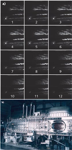
The wind tunnel itself has a 31 in. cross-section and is capable of one test per hour lasting 1 to 2 min. The fluorescent medium is pure NO injected upstream at a low flow rate. The laser light was formed into a 50 mm wide sheet directed downward from the top. Tests were carried out on trip shapes such as wedges and cylinders (a "trip" is an object that deliberately trips a laminar layer into turbulence, potentially reducing drag), with the pulse-repetition rate usually set at 500 kHz, but at 1 MHz for certain experiments; a 10 Hz slow mode is also available. A framing ICCD camera with 160 × 160 pixels and a UV-sensitive microchannel-plate intensifier captures the images.
The light sheet can be stepped through the airflow to get data at various distances from the surface. Raw images are monochrome, but processed images can be shown in false color.
To test the 1 MHz frame rate, the researchers captured an eight-frame sequence of a 2 mm tall, 4 mm diameter cylinder, locating the light sheet 0.7 mm above the surface. Even without processing, airflow phenomena are made apparent in fine spatial and temporal detail. Numerous other tests were carried out at a lower 500 MHz frame rate, which allows longer bursts of 16 to 20 pulses (and thus frames) rather than the 8 to 10 frames acquired at 1 MHz. These include image sequences of a triangular trip (see figure).
As for practical usage so far, "the system has already been used to study the detailed test object (DTO) boundary-layer trip that was mounted on the Space Shuttle orbiter," says Walter Lempert, one of the Ohio State University researchers.
REFERENCE
1. N. Jiang et al., to appear in Appl. Opt., 50, 4 (Feb. 1, 2011).
About the Author
John Wallace
Senior Technical Editor (1998-2022)
John Wallace was with Laser Focus World for nearly 25 years, retiring in late June 2022. He obtained a bachelor's degree in mechanical engineering and physics at Rutgers University and a master's in optical engineering at the University of Rochester. Before becoming an editor, John worked as an engineer at RCA, Exxon, Eastman Kodak, and GCA Corporation.
