SOFTWARE & COMPUTING: Interferometric synthetic aperture microscopy eliminates OCT compromises
Optical coherence tomography (OCT) emerged in the early 1990s as the marriage of broadband interferometry and scanning-light microscopy.1 It appears outside the laboratory today most prominently as a diagnostic tool in ophthalmology and provides axial depth ranging and—when data are acquired over additional spatial dimensions—it provides two- and three-dimensional (2D and 3D) imaging. Many OCT variants using light sources with a wide variety of coherence are now in practice and have in common the capability that data can be acquired interferometrically across a broad spectral range.
The axial resolution of OCT is proportional to the inverse of the source-detector bandwidth and so may be improved by increasing source bandwidth. The transverse resolution is inversely proportional to the numerical aperture (NA) of the optical focusing system. However, the images are only usable within the so-called confocal region—that is, within a Rayleigh range of the focal plane. Unfortunately, this confocal region shrinks as the NA is increased. Thus at some point a compromise must be made between the depth of focus (the confocal length) and the transverse resolution of the system. But with a new computed imaging technique called interferometric synthetic aperture microscopy, this compromise is no longer necessary.
Computed imaging
The emergence of a method in computed imaging requires the concurrence of developments in hardware, theory, and available computing power. For example, while the means to make measurements—the essential theory and the key numerical tool, the fast Fourier transform (FFT)—had been long established, computational power became available in the early 1970s to produce the revolutionary advances of computed tomography (CT) and magnetic resonance imaging (MRI).
In optics, the unambiguous determination of object structure without strong prior assumptions requires measurements from which the electric field (both phase and amplitude) may be inferred. The methods of holography, for instance, were developed precisely for the purposes of post-processing.2 That is, holography was proposed as a way of recording and later manipulating the field to obtain standard microscopic images. It was later observed that the hologram, or rather a series of holograms, may be seen to encode the underlying object structure and that the structure may be computed.3 For a given plane-wave illumination, the plane-wave amplitude of the scattered field is proportional to a particular element of the Fourier transform of the sample susceptibility. Diffraction tomography, as this technique came to be known, requires the acquisition of many phase-coherent holograms—a difficult accomplishment. But some good progress has been made over the years and is discussed in the literature.4
Gabor's original idea to reprocess the field to produce a better image has seen a resurgence in the digital age. In holographic refocusing methods, the digital hologram is convolved with a complex transfer function in place of a physical lens. This is accomplished in a computationally efficient way by taking a FFT, multiplying by the appropriate function, and taking an inverse FFT (iFFT). In essence, OCT provides a multifrequency hologram and the refocusing method may be applied frequency-by-frequency to effectively move the focal plane even to planes outside the Rayleigh range.5 However, the image in the plane of the original focus is then out of focus.
The key idea in diffraction tomography is to forego processing the field to obtain an intensity that better resembles the object in favor of a direct solution of the inverse problem to determine the underlying object structure. A single, 2D hologram made with monochromatic fields clearly cannot fully encode an arbitrary 3D function; hence the need for multiple holographic views in diffraction tomography. However, OCT provides multiple holograms at different frequencies from a single 2D scan, or from a single full-field image. These data are not generally enough to solve the inverse problem either since an arbitrary object is necessarily a function of three spatial coordinates and frequency. However, OCT itself is only able to provide images of structure under the assumption that the susceptibility may be written as a simple product of a spatially dependent function and a frequency-dependent function that it is separable. In that case, the inverse problem may be solved and, in principle, object structure can be reconstructed everywhere simultaneously.
A new modality arrives
A new method in computed optical imaging is thus timely. The computing power available in the modern desktop computer provides the means to process large data sets with the complexity needed to implement FFTs and interpolate data; various OCT instruments provide phase-coherent, co-registered holograms across multiple frequencies with ever-increasing speed of acquisition, and the theory is now in place to take advantage of these developments. Our team at the University of Illinois at Urbana-Champaign has solved the inverse problem for several OCT variants: planar scanning, rotational scanning, full-field, and partially coherent full-field OCT.6 We refer to these modalities collectively as interferometric synthetic aperture microscopy (ISAM), a name alluding to its connection to other synthetic-aperture techniques.7
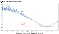
The inverse problem may be cast in a form amenable to fast implementation. In two separate asymptotic regimes, the data may be simply related to the object structure by the equationso as to obtain the Fourier transform of the susceptibility function on a uniform Cartesian grid. The 3D object is then reconstructed by dividing by the appropriately regularized value of the prefactor and taking the inverse Fourier transform. With noise-free data, the reconstruction is spatially uniform with the resolution everywhere equal to the resolution achieved in the focal plane of the system. In the presence of noise, the signal-to-noise ratio (SNR) falls off as the inverse of the distance from focus at distances larger than the Rayleigh length, but the point spread function remains unchanged as was recently verified.9 The average point-spread function with a phantom of sub-resolution-sized particles for OCT and ISAM can be measured (see Fig. 1). The oscillations seen in the OCT data result at large distance from the focus are not due to noise but instead arise because adjacent scatterers increasingly produce signals that interfere and form high-spatial-frequency structure, a phenomenon sometimes called speckle. The measurements were made using an achromatic doublet of focal length 12 mm, producing a theoretical focal-plane resolution of 4.4 μm (full-width half-maximum or FWHM) and a (free-space) Rayleigh range of 52 μm.
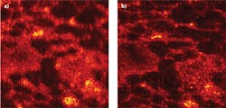
An OCT image of rat adipose tissue was obtained 53 μm below the surface and 390 μm above focus and compared to an ISAM reconstruction from the same data (see Fig. 2). The experiment is the same as described in a recent paper from Ralston and colleagues, but the depths are different.10 While the OCT image is badly defocused, the ISAM image clearly shows the adipose tissue microstructure.Among other things, ISAM enables the development of a small-form-factor instrument that has a fixed focal plane and high resolution but large depth-of-field limited only by SNR. Such an instrument could greatly expand the reach of low-coherence optical imaging in medicine. We are commercializing this technology through a company we cofounded called Diagnostic Photonics (www.diagnosticphotonics.com). Our initial target is in breast-conserving surgery or lumpectomy procedures. Here, the current standard of care includes post-operative histology for inspection of the margins of excised tissue. With ISAM, we plan to offer an in situ view of high-resolution cell and tissue microstructure over larger volumes in order to reduce re-operation rates. We expect other applications to follow.
ACKNOWLEDGMENT
The authors would like to thank Dr. Steven Adie for help in preparing images.
REFERENCES
1. D. Huang et al., Science, 254, 1178-1181 (1991).
2. D. Gabor, Proc. Royal Soc. London, 197, 454-487 (1949).
3. E. Wolf, Optical Comm., 1, 153-156 (1969).
4. O. Haeberlé et al., J. Mod. Opt., 57, 686-699 (2010).
5. J.P. Rolland et al., Proc. SPIE, 7372, 73721K (2009).
6. T.S. Ralston et al., J. OSA, A23, 1027-1037 (2006).
7. B.J. Davis et al., Sensors, 8, 3903-3931 (2008).
8. B.J. Davis et al., J. OSA, A24, 2527-2542 (2007).
9. T.S. Ralston et al., Opt. Lett., 35, 1683-1685 (2010).
10. T.S. Ralston et al., Nature Phys., 3, 129-134 (2007).
About the Author
P. Scott Carney
Associate Professor, Department of Electrical and Computer Engineering, Beckman Institute for Advanced Science and Technology
P. Scott Carney is an associate professor in the Department of Electrical and Computer Engineering at the Beckman Institute for Advanced Science and Technology at the University of Illinois Urbana–Champaign (Urbana, IL).
Stephen A. Boppart
Professor, Department of Electrical and Computer Engineering, Beckman Institute for Advanced Science and Technology
Stephen A. Boppart is a professor in the Department of Electrical and Computer Engineering at the Beckman Institute for Advanced Science and Technology at the University of Illinois Urbana–Champaign (Urbana, IL).


