IRIS DIAPHRAGMS: Liquid iris is continuously adjustable
Mechanical iris diaphragms for optical systems have been in use for 150 years. For most of this time, they were incorporated into cameras that were relatively large and expensive. Now, though, cell-phone cameras are both small and cheap; manufacturers would like to make them even smaller and cheaper. As a result, any move away from complex mechanical contraptions and toward devices that have no metal moving parts and can be fabricated at least partially using techniques from electronics manufacturing is a good move.
Gary Tsai and Andrew Yeh from National Tsing Hua University (Hsinchu, Taiwan) are making this move, having designed and tested a simple circular dielectric liquid iris.1 With no moving mechanical parts, the iris is continuously adjustable in diameter.
Applied voltage changes diameter
The force that changes the diameter of the iris is the same as the one that varies the curvature of some variable-focus liquid lenses: that arising from an electric field interacting with an induced surface-polarization charge on the dielectric-liquid surface. The force varies as the square of the applied electric field.
Two nonmixing dielectric liquids are used–a clear oil and an opaque propyl alcohol-based ink. The densities of the two liquids are almost identical, which eliminates any gravitational or inertial effects (meaning that the iris doesn't change in size and shape if the unit is tilted or moved about).
A shallow cylindrical chamber includes a flat transparent indium tin oxide (ITO)-patterned glass substrate as one of its ends, a PMMA plastic housing with a confinement ring, and a glass cover. The opaque ink naturally adheres to the edge of the circular aperture.
Using photolithography, the ITO is patterned with a set of concentric annular electrodes that push the dielectric liquid with the higher dielectric constant (the ink) toward the center when a voltage is applied; the electrode surface is also covered with a layer of Teflon. The fabricated device is 9 mm2 and 3.1 mm thick, and has an iris with an initial diameter of 4 mm.
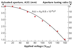
When the applied voltage is varied from 0 to 160 V, the iris changes diameter from 4 to 1.5 mm in an approximately quadratic relationship with the electric field (see figure). The total power used at the minimum 1.5 mm aperture is about 4.6 mW. The total volume of liquid within the chamber stays the same; the iris diameter changes due to the opaque ink creeping toward the center along the electrode surface.
The actuation time ranged from 0.14 s for a diameter change from 3.9 to 3.6 mm, to 1.08 s for a diameter change from 3.9 to 1.5 mm; the relaxation time ranged from 0.07 s for the change from 3.6 back to 3.9 mm, to 0.25 s for the change from 1.5 to 3.9 mm. The transmittance of the transparent portion of the iris was measured to be 85%, which could be improved with antireflection coatings on the glass surfaces.
REFERENCE
1. C.G. Tsai and J.A. Yeh, Opt. Lett., 35, 2484 (July 15, 2010).
About the Author

John Wallace
Senior Technical Editor (1998-2022)
John Wallace was with Laser Focus World for nearly 25 years, retiring in late June 2022. He obtained a bachelor's degree in mechanical engineering and physics at Rutgers University and a master's in optical engineering at the University of Rochester. Before becoming an editor, John worked as an engineer at RCA, Exxon, Eastman Kodak, and GCA Corporation.