ULTRAFAST DETECTORS: InGaAs photodiodes tackle nonlinearity and win
ABHAY M. JOSHI and SHUBHASHISH DATTA
For more than a decade, microwave photonic systems have been considered to replace their all-electronic counterparts in several applications including phased-array radar, low-noise radio-frequency (RF) oscillators, analog-to-digital converters (ADCs), and arbitrary waveform generators. These efforts have been driven by the inherent capability of processing high-bandwidth RF signals in the optical domain and transmitting them over low-loss optical fibers. However, the process of extracting the RF signals from the optical domain through photodetection invariably generates nonlinear signal distortions. This drawback has historically impeded practical deployment of microwave photonic technology in analog applications. Furthermore, the photodiodes' power-handling capability limits the optical power level and, consequently, the gain and noise figure of photonic systems. Circumventing these limitations has spurred the quest for developing highly linear, high-power photodiodes for ultrafast applications.
Pursuing linearity
A photodiode's nonlinear transfer function manifests itself in several ways. It is well known that amplitude nonlinearity compresses the RF signal, leading to the generation of unwanted harmonic and inter-modulation distortion (IMD) signals. A relevant metric to describe the resulting system limitations is the third-order output intercept point (OIP3)–the RF power level at which the third-order IMD emanating from the photodiode equals the linear signal term. In the 1990s, photodiodes having an OIP3 of 35 to 40 dBm were deemed sufficient for cable TV signal distribution, which was the primary analog application. In contrast, the emerging applications previously mentioned require 20 to 30 dB lower distortion power levels, thereby requiring photodiodes with OIP3 of approximately 50 dBm.
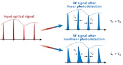
Recently, the deleterious impact of the phase noise of a photodiode on system performance has also come to the fore. Its phase linearity is defined by the rate of change of RF output phase with input optical power and is denoted as its power-to-phase conversion factor (PPC).1 Nonlinear distortion in RF phase leads to temporal distortions and is manifested as RF pulse broadening (see Fig. 1). The loss of signal integrity due to such distortions is especially detrimental to broadband systems, such as arbitrary waveform generators and chirped radars. Furthermore, the phase nonlinearity of a photodiode converts the relative intensity noise (RIN) of a laser into excess RF phase noise. The resulting increase in timing jitter limits the performance of precision optoelectronic oscillators and photonic ADCs.
Finally, it is necessary for the photodiodes to display highly linear behavior–that is, large OIP3 and small PPC at large signal amplitude and high power levels in order to maximize the link gain. High-power-handling photodiodes obviate the need for using microwave amplifiers that have been shown to degrade the overall amplitude and phase nonlinearity in a system.2, 3
To address these concerns, Discovery Semiconductors has developed a highly linear photodiode (trademarked HLPD) that demonstrates high amplitude linearity (OIP3 of approximately 50 dBm) and high phase linearity (PPC <3 rad/W) with maximum RF output power of 10 dBm (peak-to-peak amplitude of 2 V). This linear performance is obtained in both continuous-wave (CW) and pulsed operation by applying our proprietary optical beam-shaping techniques to the top-illuminated dual-depletion region (DDR) photodiode structure.4 By doing this, we can create a 22 GHz bandwidth HLPD having the aforementioned linearity and power-handling metrics at the 1550 nm telecommunications wavelength.Device fabrication
The DDR indium gallium arsenide (InGaAs) photodiode structure allows ultrafast operation in top-illuminated geometry by balancing the transit times of electrons and holes with the aid of an indium phosphide (InP) drift layer (see Fig. 2). A photodiode having 30 μm diameter active area was terminated into a 50 Ω internal resistor to achieve a 3 dB bandwidth of 22 GHz. The top-illuminated geometry also enables highly linear, high-power operation through optimization of the incident optical beam shape.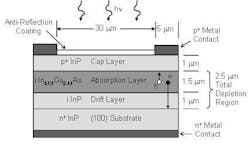
The linearity of a photodiode is limited by the space-charge screening of electric field in the intrinsic region. At high optical power levels, photo-generated carrier concentration in the depletion region can be large enough to nullify the electric field produced by the diode bias, which impedes carrier transport and causes the photocurrent to saturate. This saturation is responsible for nonlinear behavior, such as signal compression, harmonic generation, and pulse broadening. The magnitude of this space-charge screening is maximized where the illumination intensity and the resulting photocurrent density is largest. Therefore, it is desirable to achieve as uniform an optical illumination as possible across the photodiode's active area. A crucial metric for describing the quality of the optical beam shape is the ratio of the peak optical intensity to the average optical intensity in the active area of the photodiode. This peak-to-average intensity ratio should be as close to unity as possible for maximizing device linearity and power handling. In our work, we illuminated the 30 μm diameter photodiode with an optical beam having a peak-to-average intensity ratio of approximately 1.5.
Performance in CW operation
The power handling capability of a photodiode is defined by the operating point where its RF output power is compressed with respect to the ideal linear behavior by 1 dB. For our HLPD, RF output can be calculated when the device is stimulated with a CW optical signal modulated at 10 GHz frequency with approximately 100% modulation depth (see Fig. 3). In this situation, our photodiode delivers 10 dBm RF power at a 1 dB compression photocurrent of 27 mA and 5 V reverse bias. It should be noted that at higher bias voltages, the nonlinearity of the photodiode arising from the space-charge screening effect is reduced, thereby increasing its 1 dB compression photocurrent.5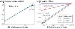
An optical phase-locked loop-based system was used to determine the photodiode's amplitude linearity at 829 MHz fundamental frequency and 63% modulation depth. Assuming memory-less nonlinearity, our photodiode demonstrates a third harmonic intercept of 54 dBm at 9 V bias, corresponding to a two-tone OIP3 of 49.2 dBm. The data also showed an improvement in amplitude linearity with increasing bias voltage.
Performance in pulsed operation
For impulse measurements, the photodiode was stimulated with a 2.5 ps wide optical pulse train generated by a 1551 nm wavelength fiber modelocked laser at 1 GHz repetition rate. The resulting RF impulse response was recorded using a 50 GHz sampling oscilloscope at different average optical power levels and reverse bias voltages. For a 9 V photodiode bias, the peak RF amplitude of the recorded waveforms displays a linear behavior up to 1.5 V peak at 9 V device bias (see Fig. 4). Assuming a triangular pulse shape for the impulse response, the PPC of a photodiode is directly proportional to the rate of change of the full-width half-maximum (FWHM) with respect to the average optical power. The derivative of the FWHM data corresponds to a PPC <3.2 rad/W at 9 V bias for up to 1.5 V peak RF amplitude. For better accuracy in determining phase linearity, the RF phase at 1 GHz repetition rate was computed from the Fourier transform of recorded impulse response. Its derivative, which equates to the PPC of the photodiode, also confirms the response value from the data. As is the case with CW linearity and power-handling metrics, increasing the photodiode's bias improves both amplitude and phase linearity in pulsed operation.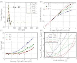
For a diverse range of analog photonic applications, these InGaAs photodiodes have broad wavelength coverage from 800 to 1650 nm. The HLPD photodiode presented here at 1550 nm also demonstrates similar amplitude and phase linearity at 900 nm, further magnifying the potential impact of these devices in microwave photonic systems.6
REFERENCES
1. A. Joshi and S. Datta, IEEE Photon. Technol. Lett., 21, 1360-1362 (2009).
2. K.J. Williams and R.D. Esman, J. Lightwave Technol., 17, 1443-1454 (1999).
3. S. Datta et al., "High Phase Linearity, High Power Handling, InGaAs Photodiodes for Precise Timing Application," OFC Conference, oral presentation OWX2, San Diego, CA (2009).
4. A. Joshi, S. Datta, and D. Becker, IEEE Photon. Technol. Lett., 20, 1500-1502 (2008).
5. A. Joshi and D. Becker, "GRIN Lens-Coupled Top-Illuminated Photodetectors for High-Power Applications," IEEE Intl. Topical Meeting on Microwave Photon. (MWP), conference paper 9017, Victoria, BC, Canada (2007).
6. J. Taylor et al., "Photodiode Limitations in the Generation of Low-Noise Microwave Signals from Stable Frequency Combs," IEEE Intl. Topical Meeting on Microwave Photon. (MWP), conference poster paper Th4.2, Valencia, Spain (2009).
Abhay M. Joshi is president and CEO and Shubhashish Datta is a photonics engineer at Discovery Semiconductors, 119 Silvia St., Ewing, NJ 08628; e-mail: [email protected]; www.discoverysemi.com.