ULTRAHIGH-SPEED IMAGING: Taking the hype out of hypervelocity
Traditionally, ultrahigh-speed framing cameras have been deployed in the science of very fast phenomena, such as high voltage discharge, crack propagation, detonics, and hypervelocity particle-impact studies. These traditional sciences have now been joined by biomedical and botanical studies, nanotechnology, and space research, where the speed of image capture is not always the most important factor—and in some cases, speeds of 500,000 frames per second (fps) or less are acceptable. However, the ability to "freeze" the motion and obtain high-quality, high-resolution imagery that allows detailed, accurate analysis is of the utmost importance. In the past, a good sequence of pictures from the event was enough, but nowadays, accurate timing, high resolution, and short exposures are required as the data from the images are often correlated with simulation data and then used to adjust numerical models that deepen the understanding of the physical processes involved.
A new imaging engine
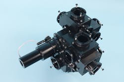
Until recently, ultrahigh-speed cameras using beamsplitter designs were either too large and/or had image artifacts such as vignetting, parallax, and astigmatism. Specialised Imaging worked in conjunction with optical design company Resolve Optics Limited (Bucks, England) to develop the beamsplitter-based SIM camera that eliminates the usual optical aberrations that limit the effectiveness of multichannel framing cameras.
Optical-modeling software tools enable a compact, folded-optics design that maintains equal transit times for all wavelengths input to the SIM camera's 16 viewports. Because it is impossible to predict the wavelength of light that enters the beamsplitter, special attention was given to the lens design such that the focal plane is coincident for all visible wavelengths from 350–900 nm (see Fig. 1). Each viewport on the beamsplitter is equipped with an 18 mm high-resolution image intensifier coupled to a 1380 × 1040 pixel interline-transfer CCD sensor.
The intensified CCD (ICCD) sensors were developed specifically for the SIM camera by Photonis (Bordeaux, France), and with a 6 µm pitch microchannel plate (MCP) with six million channels, resolution is a staggering 50 line pairs per millimeter (lp/mm). Exposures as short as short as 3 ns are produced by rapidly turning on and off the photocathode that then functions as a very fast shutter. The phosphor screen at the output of the intensifier has a relatively slow decay that allows the CCD sensor enough time to capture the image.
Because the MCP multiplies the electrons and provides variable gain as the potential across the plate is varied, the sensitivity of all the ICCD units inside the camera can be matched, providing the fine control necessary to vary the sensitivity from frame to frame when taking images of events that have a rapid increase or decrease in intensity (such as explosive events, plasma, or electrical discharges). The combination of a fine-pitch MCP and a fine-grain, high-sensitivity P43 phosphor carefully coupled to the CCD sensor using a low-distortion 4 mm fiber-optic stub enables the 50 lp/mm resolution.
The analog video signal from each channel's CCD sensor is digitized to 12 bits using a dedicated video signal processor located close to the ICCD to minimize any noise and interference before being transmitted to the main control electronics. A large field-programmable gate array (FPGA) device is then used to multiplex the eight separate 12-bit data channels into a single block of high-speed memory where the image sequence is held until required for download to the controlling personal computer (PC). Dealing with this amount of high-speed data requires very careful printed-circuit-board (PCB) design and layout to avoid unnecessary noise introduction.
Flexible control
Capturing rapid events that develop over a few seconds requires careful control. But imaging phenomena that last a millionth of a second or less requires both extremely fine control of the timing and a sophisticated triggering system that has to remain simple yet flexible. The triggering system on the SIM series of cameras is capable of accepting any electrical signal in the range of -50 to +50 V. The trigger signals are sampled at 1 GHz, allowing detection of pulses as short as 2 ns with very good repeatability (and with <1 ns jitter). The triggering is further enhanced by the SURESHOT facility that utilizes two separate trigger inputs. First, SURESHOT relies on two trigger points a known distance apart to measure the velocity within 1 ns. Second, by knowing the distance from the triggers to the camera's field of view, the timing circuits can calculate the exact delay required to reliably capture the first image of a moving object at a predefined point within the field of view. Using this facility, users can pinpoint the exact moment to start recording, even when velocities are variable or unpredictable.
Once a trigger is received, it is fed into a high-speed timing generator that synchronizes all of the ICCD channels to enable frame rates up to 1 billion fps, admittedly with overlapping shuttering times. A unique random-access-memory (RAM)-based timing generator within the FPGA allows leading-edge to leading-edge shuttering pulses from 1 ns to 10 ms. Complex algorithms allow independent control of each ICCD channel with exposure timings from 3 ns to 10 ms in 1 ns steps. The timing signals are then converted into a train of high-voltage pulses to turn the image intensifiers on and off at the appropriate times.
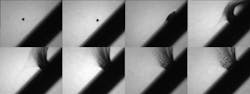
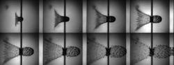
Hypervelocity in action
The study of hypervelocity micro-particle impact events is one of the most taxing experiments because there is often uncertainty in the velocity of the projectile, and the images are normally taken with high magnification in a small 2–4 cm2 field of view (FOV). The projectiles typically travel between 2 and 5 km/s; therefore, even the slightest variation in velocity can result in either capturing or completely missing the event. At 1 km/s, an image taken with a 1 µs exposure will produce a 1 mm motion blur, which is unacceptable if the FOV is only 6.3 × 5 cm—especially if analytical data is required from the image.

Acknowledgment
The authors would like to thank P. Hereil, A. Lachaud, and J. Mespoulet of Thiot-Ingenierie (Bretenoux, France) for the experimental data and results.
REFERENCES
- A.J. Piekutowski, Int. J. Impact Eng. 23, 711–722 (1999).
- P.L. Hereil et al., Centre d'Etudes de Gramat Report T2001-00059/CEG/NC, Gramat, France (2001).
- J.M. Sibeaud et al., Int. J. Impact Eng. 29, 647–658 (2003)
- Q. Zhang et al., Int. J. Impact Eng. 35, 1884–1891 (2008).
About the Author
Keith Taylor
Keith Taylor is a director of Specialised Imaging (Pitstone, U.K.).