OPTICAL MANUFACTURING: Life sciences can challenge optics manufacturers
ANDREW LYNCH
Biomedical optical technology has evolved considerably since the invention and proliferation of the microscope in the 17th and 18th centuries. The advent of new techniques has continually added to the complexity of biomedical optical instrumentation such as medical lasers, flow cytometers, and modern microscopes. These system complexities place ever-increasing demands on the optical components they use—demands that translate into requirements that can challenge the optics manufacturer. An appreciation of these manufacturing challenges can help savvy biomedical device companies intelligently push system performance forward while still operating within the bounds of feasible manufacturability.
UV wavelengths
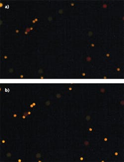
Despite the wide-ranging and disparate nature of biomedical applications, there are some common themes that place difficult requirements on the optical components used. The need to use ultraviolet (UV) light is one such theme. An application may need to go into the UV for several reasons. In ophthalmology, for instance, refractive surgery (LASIK or laser-assisted in situ keratomileusis) benefits from the more energetic nature of UV light (compared to visible light) and the higher precision available at the shorter wavelengths. And in fluorescence microscopy, a sample may need to be excited and/or imaged with UV light (see Fig. 1). From the manufacturing point of view, the difficulties of working within the UV are the limited availability and breadth of transparent materials, the relative cost of such materials, and the relatively higher-precision optical requirements.
The most common optical materials used at UV wavelengths are fused silica and quartz; some fluoride-based materials, such as calcium fluoride, magnesium fluoride, and barium fluoride; certain alkali halides such as sodium chloride; and some other crystals like sapphire. Compared to the more common optical glasses used at visible wavelengths, these raw materials can range from twice to ten times as expensive or more. And further cost accumulation typically continues on the fabrication side.
Silicates are relatively easy to work and polish, but many of the other materials mentioned are not. Compared to glass, many materials exhibit different hardness properties, thermal properties, or fracture properties, or they may require certain environmental precautions during both manufacture and end use. The alkali halides, for instance, are notoriously hygroscopic, so they require nontraditional polishing solutions during manufacture, and special care must be taken during storage and use. Water absorption can be reversed in vacuum ovens but the overall problem is still omnipresent. In contrast and further illustrative of the differences between materials, sapphire, which is the second hardest crystal in nature after diamond, requires diamond-based polishing agents because regular polishing compounds would not work.
Many of these materials also exhibit a low index of refraction in the UV. This means that for a focusing lens fabricated from one of these materials to focus UV light, it would require a curvature comparatively higher than a material with a larger refractive index. The catch here is that the higher the curvature, the lower the number of lenses that can be polished at the same time, which translates to a higher per-piece cost. A well-known work-around for this issue is to "split" a lens into more than one element to share the work of bending the light. This trick does less to save on cost than it does to help guard against other unwanted side effects—like optical aberrations—but it does remain a tried and true option.
Given the relative costs and difficulties of available UV-transparent materials, it's clearly in an optical designer's best interest to fully understand the material limitations. In some cases, certain material choices will be unavoidable, but there are still many instances when expensive UV materials are used where fused silica would suffice—and even where fused silica is used when more common glasses may be adequate.
A prime example is certain optical filter applications that either block or transmit UV light during fluorescence experiments. For the filter substrates, many designers immediately choose to use fused silica because it exhibits virtually no autofluorescence (unwanted fluorescence from the fused silica being exposed to UV light). In many cases, these designers have, of course, made the right choice, but there are probably just as many situations where less expensive, ubiquitous glass material could have been used successfully instead. This can be especially true where unwanted light can be blocked earlier in the optical layout or perhaps naturally through various absorptions and back reflections.
Both N-BK7 and Borofloat are examples of glass materials that have been used successfully for high-end filters, thanks in part to modern optical coating technology that enables increasingly better transmission-to-blocking (signal-to-noise) ratios. As cheaper materials (compared to fused silica), these are welcome alternatives for systems that, by design, must contain a number of unique, high-end filters. A good example of such system-level devices in this case would be the various highly competitive fluid/chemical analyzer and flow cytometry markets.
Even with all the modern advances, optical coatings are no less immune to the difficulties of biomedical application requirements. As with optical substrates, coating materials that work in the UV are few and are similarly expensive. Common UV coating materials include hafnium oxide, scandium oxide, silicon dioxide, and aluminum oxide. Many coating materials in general are also relatively soft and, again, hygroscopic. There is no blanket advice to be given here except that it can pay dividends to work closely with companies that offer access to coating design support.
Medical lasers
There are, of course, other optical challenges inherent to biomedical applications besides the ultraviolet. Medical lasers, regardless of wavelength, typically have high-power beams associated with them that stress the optical coatings, surfaces, and materials alike. To be compatible with these lasers, the optics require more stringent specifications, as compared to lower-power applications.
Coating and substrate materials must be chosen carefully to minimize bulk absorption effects that otherwise could quickly lead to catastrophic failures. Glasses should be comparatively bubble- and inclusion-free, and in general, as homogenous as possible. Coatings—one of the main sources of failure of an optic exposed to a high-power laser—must be comparatively free of defects. Common coating defects include microscopic pinholes (coating voids), metallic nodules (inclusions inherent in common coating materials), and other possible absorption sites such as foreign debris. Optical surfaces must also be polished ever finer to eliminate as many surface scratches and digs as possible that arise naturally from the polishing process. These higher precision efforts are all critical to avoiding possible sources of high-power laser absorption, which can burn, crack, or even shatter an optic.
Continuing with the medical laser example, it is easy to extrapolate the precision requirements discussed into a broader discussion of tighter optical specifications and tolerances often now required by biomedical optics. Optics for laser-based surgery demand all-round very tight tolerances to eliminate defocus or scattering problems due to a lens shape or other imperfections being different from nominal that could lead to unexpected surgical results, or worse, patient injury.
Microscopes
Modern microscope systems are amongst some of the most complicated optical devices available today. They can incorporate a multitude of optics to support various channels and capabilities. Along with the traditional objective-to-eyepiece path, there are often dedicated optical paths for cameras, detectors, and spectrometers, as well as various illumination schemes (including laser and/or nonlaser sources). All these paths demand pristine optics in order to function in harmony. The main objective lenses—arguably the optical sub-assembly most burdened by the various optical paths of modern microscopes—have accordingly evolved into wonders of optical design, manufacture, and assembly. Due to the need to use more exotic materials, multiple precision optical elements, and active alignment practices during assembly, some microscope objectives can even rival the cost of a brand new car.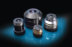
Biomedical device companies often know general performance requirements of a given optical component within their system, but they may not always know what specifications can give them the performance they need while still staying within the realm of cost-effective manufacturability. This is especially true for systems that require multiple optical components and multiple optical paths (see Fig. 2). Often, cost-saving component modifications can be suggested by optical component manufacturers once they understand what the system needs to accomplish. A general appreciation for the manufacturing difficulties of biomedical optics, along with active involvement of designers and manufacturers alike at both the design and quotation stages, is critical for the success of biomedical optics projects.
FURTHER READING
1. H.H. Karow, Fabrication Methods for Precision Optics, New York: J. Wiley & Sons (2004).
2. R.E Fischer, B. Tadic-Galeb, and P.R. Yoder, Optical System Design, New York: McGraw-Hill (2008).
Andrew Lynch is a solutions engineer at Edmund Optics, 101 E. Gloucester Pike, Barrington, NJ 08007; e-mail: [email protected]; www.edmundoptics.com.