FIBER & PREFORM FABRICATION: Novel fiber fabrication methods benefit fiber lasers
MRIDU P. KALITA, ANDREW S. WEBB, ALEXANDER J. BOYLAND, SEONGWOO YOO, and JAYANTA K. SAHU
Industrial fiber-laser manufacturing is emerging as one of the fastest-growing sectors for silica optical fibers. Fiber lasers exhibit many advantages over their diode-pumped solid-state counterparts such as superior performance, excellent reliability, compact size, and high efficiency that results in a cost savings for the user. In particular, the ytterbium (Yb)-doped fiber laser has been singled out for power scaling to multi-kilowatt output levels in both continuous-wave and pulsed regimes.1 The increase in applications using Yb-doped fiber laser sources has spurred the development of various types of silica fibers, each with a unique set of properties to match the specific product application. And because the design and material properties of the glass have become critical to the performance of the fiber laser, advances in optical fiber and preform manufacturing are ongoing.
Most silica optical fibers are drawn from preforms manufactured using modified chemical-vapor deposition (MCVD). The method is well-suited for fabricating passively doped transmission fiber but is less-well equipped for incorporating rare-earth ions into the glass structure of the preform. An established technique known as solution doping is used for this purpose, but is impractical for realizing fibers with multiple layers and of complex design.2 To bridge the gap between the ongoing demand for fiber lasers and current rare-earth-doping capabilities, the Optoelectronics Research Centre (ORC) at the University of Southampton (Southampton, England) has pioneered two techniques known as in-situ solution doping and chemical-in-crucible deposition.3,4
In-situ solution doping
In conventional solution doping, a layer of silica particles—called "soot"—is first deposited on the inside of a high-purity glass substrate tube (see Fig. 1). The soot is only a few tens of microns thick, but its large surface area gives it high porosity. This layer eventually forms the guiding core of the optical fiber. Following deposition, the glassware is disassembled from the preform-making lathe and transferred to a separate piece of apparatus where a solvent solution containing the required rare-earth and co-dopant ions, such as aluminum, is administered. After a specified soaking period (normally 1 hr) the tube is returned to the lathe and the glassware is once again set up. The layer is then sintered at high temperature into a glassy layer. This process must be repeated for each layer which results in an overall reduction of usable preform owing to the continued removal process. It is therefore unsuitable for more than three to four doped layers.
The MCVD in-situ doping technique is similar to conventional solution doping, but the need to remove and reassemble the glass on the lathe is eliminated making the process more efficient, reliable, and improving preform yield. The process first involves depositing a soot layer as previously described. Next, the solvent solution is introduced into the soot from the tailstock end of the assembly. A small-diameter glass tube is pushed upstream until it is in close proximity to the soot layer while the other end of the tube is attached to a flexible hose that delivers the liquid solution via a pump. The glassware remains in position throughout this process. Once the soot is completely soaked, the feed tube is removed and the solvent is left to evaporate, leaving the rare-earth ions behind. The layer is then completely dried and the doped oxide particles are sintered into glass. Finally, the tube is collapsed and sealed to produce the solid glass preform. Multiple layers can be produced by repeating this doping process with the composition of each layer altered according to the preform recipe.
The flexibility of the in-situ doping technique makes it possible to realize complex rare-earth-doped preform geometries that are impractical to fabricate through conventional solution doping. An example is the Yb-doped "pedestal" fiber that features a raised inner cladding ring around the core to offset its high numerical aperture (NA), typically > 0.15, caused by the high doping concentration (see Fig. 2). Using the in-situ doping approach, the effective core NA can be reduced to approximately 0.06 and be few-moded at the lasing wavelength.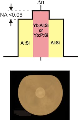
To ensure optical guidance occurs in the designated core, a large-diameter inner cladding—consisting of several deposited layers—is needed in the preform. Phosphorus or germanium precursors are the usual choice in MCVD as a plurality of layers can be deposited in the vapor phase. However, the resultant glass is inherently stressed and prone to cracking. But by using the in-situ technique, several or more individual layers of a non-stressed aluminosilicate material can be deposited for the inner cladding. As an example, thanks to in-situ solution doping, a 400 μm diameter fiber with a single Yb-doped core consisting of 14 aluminosilicate raised inner-cladding layers has been demonstrated (see Fig. 2). The fiber was drawn into a double-cladding geometry, enabling an Yb-doped fiber laser efficiency (optical-to-optical) of approximately 80%.
Chemical-in-crucible deposition
In addition to in-situ solution doping, a second technology in development at ORC is the chemical-in-crucible technique, designed for the vaporization and subsequent incorporation of relatively low-volatility precursors. The current focus is on lanthanide-based chelate complexes that are solid at room temperature but sublime at around 150° to 200°C. Deposition systems that use these precursors are commercially available but were originally developed for making telecom fibers with low rare-earth concentrations. As a result, their development for high-power laser applications has not been reported widely, possibly due to the practical difficulties in implementing an external rare-earth delivery system.
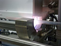
The MCVD chemical-in-crucible technique allows heating of the rare-earth precursor directly within the MCVD glassware on the lathe in close proximity to the deposition zone, increasing the versatility and maintaining better uniformity along the length of the preform (see Fig. 3). The rare-earth or co-dopant precursors are placed in a crucible that is electrically heated by an external power supply and temperature-controlled to within 1°C.
The high volatility of the lanthanide-based chelate complexes in conjunction with MCVD offer excellent opportunities to dope preforms with rare-earth ions both in the gas-phase and to very high concentrations at moderately low temperatures of around 200°C. Since the incorporation of the RE and modifier ions such as aluminum and phosphorus, for example, takes place simultaneously with the silica deposition, there is the additional benefit of significantly less rare-earth clustering for the equivalent doping level when compared with the solution-doping technique. This novel chemical-in-crucible preform fabrication technique offers potential for gas-phase deposition of a wide range of precursors, with the flexibility of heating them to several hundreds of degrees centigrade if necessary to produce sufficient vapor.
REFERENCES
1. Y. Jeong et al., Opt. Exp., 12, 25, 6088-6092 (2004).
2. J.E. Townsend et al., Electron. Lett., 23, 7, 329-331 (1987).
3. A.S. Webb et al., J. Non-Crystalline Solids, 356, 848-851 (2010).
4. A.J. Boyland et al., CLEO/QELS 2010 paper CThV7, San Jose, CA (May 2010).
Mridu P. Kalita was a PhD student at the Optoelectronics Research Centre (ORC) at the University of Southampton and is currently with Fianium Limited (Southampton, England). Andrew S. Webb is a PhD student, Alexander J. Boyland and Seongwoo Yoo are research fellows, and Jayanta K. Sahu is principal research fellow at the ORC, University of Southampton, Highfield, Southampton, Hampshire SO17 1BJ, England; e-mail: [email protected]; www.orc.soton.ac.uk.