NANOIMAGING: Bilayer metamaterial lens breaks the diffraction limit
HUIKAN LIU and KEVIN J. WEBB
All conventional lenses, no matter what their numerical aperture, are subjected to Abbe’s diffraction limit. The reason is that the evanescent light waves emanating from the object, which carry the information on the object’s subwavelength features, decay exponentially as a function of distance from the object and are thus effectively nonexistent at the image plane.1 Various schemes have been developed to break the diffraction limit. One example is the near-field scanning optical microscope (NSOM), in which near-field probes such as tapered waveguide apertures and metallic and dielectric tips scan the sample surface.2, 3
More recently, the notion of a negative-refractive-index “superlens” for imaging beyond Abbe’s limit was proposed and validated with transmission lines at microwave frequencies and with negative-permittivity slabs at optical frequencies.4, 5, 6 One way to explain this behavior is through the resonant enhancement of the evanescent fields associated with the surface waves (also referred to as surface-plasmon polaritons) of negative-refractive-index materials, offering enhancement at the focal point.
Because resonant losses and material absorption severely limit the performance of these superlenses, particularly at visible wavelengths, other structures have been proposed to achieve subdiffraction imaging. Among these are optical anisotropic metamaterials, which hold promise for subwavelength imaging systems that have lower losses and wider bandwidths.7, 8, 9
The anisotropic route to subwavelength imaging
Unlike isotropic materials in which the permittivity ε and the permeability µ are scalar numbers, anisotropic media have tensor ε and/or µ, and exhibit interesting properties. For example, negative refraction can occur at certain incident angles in an anisotropic material.10
If a metamaterial is used, a strong anisotropy can be created that can lead to a much wider variety of physical phenomena, which can lead to important applications. Metamaterials are artificially engineered materials patterned on a subwavelength scale to achieve predesigned properties that cannot be realized by naturally occurring materials.11
Anisotropic materials, and in particular those that are uniaxially anisotropic, can be synthesized for use at IR and visible frequencies by creating periodic composite structures such as multilayer metal-insulator stacks or nanoinclusions embedded in a dielectric host, provided the periodicity is much smaller than the operating wavelength. The resulting effective medium is typically characterized by two variables: ε⊥, the permittivity component perpendicular to the material surface, and ε||, the permittivity component parallel to the surface.
An anisotropic metamaterial can achieve subwavelength imaging when incident evanescent waves with a large transverse wave number are converted to propagating waves inside the medium; this occurs when the relation ε⊥ε|| < 0 is satisfied. The Poynting vectors of these waves form a diverging conical surface extending outward from the source, along which the major portion of the transported power is concentrated, with the half-angle of the cone determined by ε⊥ and ε||. The strongly confined beams in the material (known as resonance cones) carrying the subdiffraction features can then be transferred in a raylike manner to the image plane.
Until now, two classes of nonmagnetic metamaterials exhibiting strong anisotropy have proven most promising for subwavelength imaging: anisotropic lenses operated in the so-called “canalization” regime with ε⊥ approaching infinity and total thickness being a multiple of half-wavelengths, and lenses based on coupled surface modes in a metal-insulator stack in which ε⊥ approaches infinity and ε|| approaches zero.
While the former approach has been experimentally demonstrated at microwave frequencies by using a metallic-rod array, its performance is limited by stringent requirements on the material thickness and operating wavelength.12 The latter approach, on the other hand, gives rise to electrically thin slabs and therefore does away with the limitation on the material thickness.
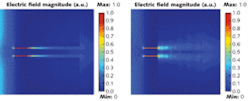
In one example, a simulation compares a double slit imaged through a bulk anisotropic slab (determined from an effective medium calculation for equal silver/silica–Ag/SiO2–volume fractions) to the same double slit imaged through a metal-insulator stack version (see Fig. 1). The simulation clearly shows a pattern of confined beams with subwavelength resolution. As the figure demonstrates, the metal-insulator stack is a good candidate to realize strongly anisotropic media.
From single layer to bilayer
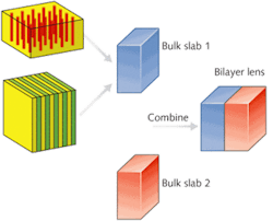
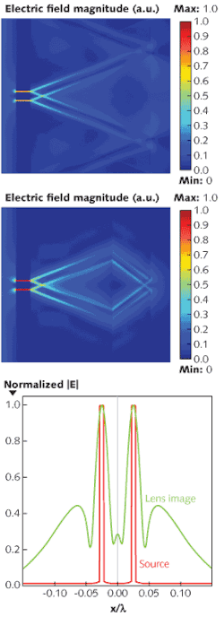
Although the stack-based anisotropy strategy lessens the impact of material absorption, a strict limitation on operating wavelength remains because of material dispersion: namely, the permittivities of the metal and the insulator must be matched. The working wavelength for a single Ag/SiO2 bulk anisotropic lens is restricted to the region around 350 nm. To address this issue, we investigated a nonmagnetic bilayer lens that can achieve subwavelength resolution and be designed to work at virtually any wavelength (see Fig. 2).As opposed to a perfect lens, which exploits magnitude compensation of evanescent fields, the anisotropic bilayer slab lens depends on phase compensation, leading to constructive superposition of subwavelength components and image resolution beyond the diffraction limit. As a result, the imaging performance of the bilayer lens is more sensitive to phase compensation than to impedance match. We found that the performance is robust when the lens has a moderate impedance mismatch; however, a large impedance mismatch between the two layers could cause multiple reflections. The rule of thumb is that because phase compensation impacts more strongly on the imaging performance, it should be prioritized in practical designs of bilayer lenses.
REFERENCES
- M. Born and E. Wolf, Principles of Optics, 7th edition (Cambridge University Press, 2002).
- S. Kawata et al., Nature Photonics 29, p. 388 (2009).
- B. T. Rosner and D. W. van der Weide, Rev. Scientific Instruments 73, p. 250 (2002).
- J. B. Pendry, Phys. Rev. Lett. 85, p. 3966 (2000).
- J. Zhu and G.. V. Eleftheriades, Phys. Rev. Lett. 101, p. 013902 (2008).
- N. Fang et al., Science 308, p. 534 (2005).
- K. J. Webb et al., Phys. Rev. E 70, p. 035602, (2004).
- H. Liu et al., Optics Lett. 33, p. 2568 (2008).
- H. Liu et al., Optics Lett. 34, p. 2243 (2009).
- J. A. Kong, Electromagnetic Wave Theory (EMW Publishing, Cambridge, MA, 2005).
- V. M. Shalaev, Nature Photon. 1, p. 41 (2007).
- P. A. Belov et al., Phys. Rev. B 77, p. 193108 (2008).
Huikan Liu is a graduate research assistant and Kevin J. Webb is professor of electrical and computer engineering at Purdue University, West Lafayette, IN 47907; e-mail: [email protected]; www.purdue.edu.


