WAVELENGTH METERS: How to select a wavelength meter
Wavelength meters are tabletop instruments that return immediate high-accuracy wavelength values for pulsed and continuous-wave laser sources, and they provide high-accuracy monitoring of tunable lasers and diode lasers. Although there are many ways to measure laser wavelength, wavelength meters provide accuracy far beyond that of a spectrometer or grating monochromator, which provide everyday wavelength measurements to accuracies around a tenth of a nanometer. Wavelength meters can provide accuracy ranging from 0.01 nm to hundredths of a picometer (pm), and they can monitor the wavelength of tunable lasers or lasers subject to wavelength drift, without the use of cumbersome, time-consuming long-path techniques that a spectrometer would require.
Wavelength meters are useful for applications in which high accuracy in laser wavelength is required. “Most customers come from university labs that are doing spectroscopy, or companies that want to stabilize a laser while doing spectroscopy,” says Nils Hommerstad, sales manager of scientific diode lasers and wavelength meters at Toptica Photonics (Graefelfing, Germany). “For example, in rubidium (Rb) or elemental spectroscopy, you need absolute wavelength information on the laser, where absolute accuracy indicates the maximum wavelength error allowed as a result of environmental conditions.” Tunable laser applications, such as cooling/trapping and , also require wavelength meters, as does testing and manufacturing of dense wavelength-division-multiplexing (DWDM) equipment for optical communications.
Michelson vs. Fizeau
A wavelength meter typically consists of a photosensor (such as photodiode arrays or a CCD), photoamplifiers, a thermostat, a device to split and measure the light (two or more interferometers), and software to error-correct the signal, then calculate and display the wavelength. Most devices come with software that displays the wavelength data on a computer via a high-speed USB interface; others display the data on the device console.
The most common high-accuracy wavelength meters are based on interferometers, typically either Michelson or Fizeau. The scanning Michelson interferometer splits the incident beam between a fixed path and a smoothly varying path. Both beams reflect back and recombine at a beamsplitter to produce a sinusoidal interference pattern. Next, the device calculates the unknown wavelength of the incident light, λ, using the Michelson interferometer equation: mλ = 2nd, where m is the number of fringes detected across a distance, d, scanned by a scanning mirror. The refractive index, n, is typically that of air. The accuracy of this wavelength calculation depends on the precision of the scanning mirror displacement, so the Michelson-based device incorporates a reference laser with a wavelength known to high accuracy. The reference laser is measured at the same time as the scanning mirror displacement to determine the incoming laser wavelength.1
The Fizeau-based meter has the advantage of a solid-state design (no moving parts), making it insensitive to intensity fluctuations and sidemodes. Because it has no scanning mirror or reference laser, a solid-state design also eliminates the need for power. The Fizeau system has two stacked reflective plates at a slight angle, forming a wedge that reflects the incident laser light to produce a pattern of parallel fringes, which is then imaged onto a photodiode array.2 Like the Michelson wavelength meter, the device then analyzes the signal and computes the wavelength of the laser.
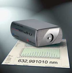
Currently, the highest accuracy wavelength meters on the market are Fizeau-based (see Fig. 1), but there are caveats, says Brian Samoriski, president of Bristol Instruments (Victor, NY). Fizeau wavelength meters are more expensive, and they are limited to measuring wavelengths below 2.25 µm. Furthermore, high absolute accuracy of up to ±2 MHz (±0.005 pm at 800 nm) requires frequent calibration (up to once per minute) using stabilized reference lasers with wavelengths known to better than 1 MHz.3 If that level of accuracy is your goal, look for an autocalibration feature to self-correct the signal frequently. Alternatively, you may want a system for which the automatic calibration turns on only once each week to keep the wavelength accuracy measurement around ±100 MHz.
Next to laser wavelength, the most important specification to tackle when shopping for a wavelength meter is accuracy: the resolution you can expect in the readout. Commercially available wavelength meters generally fall into three accuracy categories: ±0.0002 nm at the high end, ±0.001 nm at mid-range, and ±0.01 nm at the low end (although this is still considered high accuracy).
Apples to oranges
When comparing the stated accuracy of wavelength meters, you’ll quickly discern that manufacturers’ specifications use several variations in units. Some companies specify accuracy in nanometers or picometers (pm), but often the wavelength resolution is given in terms of frequency units (gigahertz or megehertz). Why are frequency units common for a measurement of linewidth? “Different groups and applications speak different languages,” says Mark Tolbert, president/CEO at Toptica USA (Victor, NY). For example, frequency metrics are preferred by signal engineers, while wavelength metrics are preferred by optical engineers. “We use megehertz to define the resolution of wavemeters, as it represents the entire range of our device,” says Tolbert. “For example, our WS7 is specified at ±60 MHz for 350 to 1120 nm–the entire range of the device. We could say the resolution is as good as ±0.02 pm, which may sound impressive, but that value is only true at 350 nm of wavelength. At 1064 nm, the accuracy becomes ±0.23 pm.”
To convert an accuracy value given in frequency units, Δf (in Hz), to a wavelength range, Δλ, with units of length, use:
Δλ = (λ2/c) Δf
where λ is the operating laser wavelength in meters, and c is the speed of light (3 × 10⁸ m). And be careful with unit conversion.
To further complicate comparison shopping, some companies provide wavelength accuracy values in units of parts per million (ppm). Stefan Loeffler, product manager at Agilent (Santa Clara, CA), explains that “1 ppm” is 1/1000000 of the displayed wavelength value, or 0.0001% of the displayed value. “We use ‘ppm’ when uncertainty is linearly dependent on the displayed wavelength, and when other metrics would lead to very small numbers with many trailing zeros like 0.0001%.” For telecom wavelengths, an accuracy of ±1 ppm of 1550 nm is equivalent to ±1.55 pm, while ±1 ppm of 1480 nm is equivalent to ±1.48 pm. If you find that converting “apples to oranges” when comparing specification sheets is bothersome, ask the technical sales person to provide the accuracy values in the units that suit your application.
Beyond wavelength accuracy, the confidence in the measurement is an important detail and should not be overlooked. “Some customers only review the accuracy specification. If the wavelength meter meets their accuracy requirement, they may be satisfied,” says Samoriski. “For confidence in the ultimate experimental results, it’s extremely important that users dig a bit deeper to understand how the manufacturer guarantees the specified accuracy.”
The type of laser you have and your application will help you narrow down the selection further. For CW lasers, scanning Michelson interferometer technology is a reliable choice. Fizeau interferometer technology can measure both CW and pulsed lasers (and so can some Michelson devices). To measure several lasers at once, a Fizeau-based device with its high repeatability rate combined with a multifiber or multichannel switcher will do the job. Multiwavelength meters are designed to analyze a DWDM signal that has many optical wavelengths present at the same time (see Fig. 3). Most wavelength meters have a fiber-optic feed from the laser to the device, and some require only a few nanowatts of light to operate, which might be obtained using only stray light, depending on the power of your laser. Fiber coupling attenuates strong laser light to protect the CCD detector. If your application involves stabilizing one wavelength source to another, proportional integral and differential (PID) control is an option to look for in the device software, along with features like linewidth readout, a Windows-based interface, and choosing the wavelength metric of your choice.
REFERENCES
- documents.exfo.com/appnotes/anote154-ang.pdf
- S. Dyer, Survey of Instrumentation and Measurement, John Wiley & Sons, NY, NY (2001).
- www.toptica.com/products/itemlayer/59/080505_WSU.pdf
Editor’s note: The “Product Focus” series is intended to provide a broad overview of the product types discussed. Laser Focus World does not endorse or recommend any of the products mentioned in this article.
About the Author
Valerie Coffey-Rosich
Contributing Editor
Valerie Coffey-Rosich is a freelance science and technology writer and editor and a contributing editor for Laser Focus World; she previously served as an Associate Technical Editor (2000-2003) and a Senior Technical Editor (2007-2008) for Laser Focus World.
Valerie holds a BS in physics from the University of Nevada, Reno, and an MA in astronomy from Boston University. She specializes in editing and writing about optics, photonics, astronomy, and physics in academic, reference, and business-to-business publications. In addition to Laser Focus World, her work has appeared online and in print for clients such as the American Institute of Physics, American Heritage Dictionary, BioPhotonics, Encyclopedia Britannica, EuroPhotonics, the Optical Society of America, Photonics Focus, Photonics Spectra, Sky & Telescope, and many others. She is based in Palm Springs, California.


