DISPLAYS: Electrofluidic display uses brilliant color pigments
Researchers at the University of Cincinnati and Sun Chemical (both in Cincinnati, OH) have developed a lithographically fabricated electrofluidic display that uses visually brilliant color pigments and reaches a reflectivity value of 55% with future potential to reach 85%. The new technique differs from electronic-paper (e-paper) displays that use oils, dyes, or interference effects—such as electrowetting, electrophoretic, cholesteric liquid-crystal, or microelectromechanical systems (MEMS) interference-based displays —to achieve high-reflectivity (typically 50%) color. 1
Biomimetics in action
The researchers selected the term “electrofluidic” because the display is based on the charge-induced movement of liquids through microfluidic cavities. “This is not electrophoretic, where you move pigments inside a liquid,” says Jason Heikenfeld, assistant professor at the University of Cincinnati. “Instead we actually move the whole liquid, which carries along the pigments, resulting in much higher contrast and color saturation.”
The electrofluidic structure includes a reservoir that holds an aqueous pigment dispersion in less than 5% to 10% of the visible pixel area, while also containing a surface channel that occupies 80% to 95% of the visible area. The technique is biomimetically inspired by squids and chameleons, which use a similar movement of pigments within their bodies to change colors.
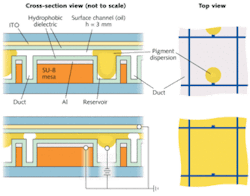
The smaller, cylindrical reservoir and the larger planar pixel structure are both fabricated in a single, inexpensive photolithographic or microreplication step (see figure). Fabrication consists of several coatings to form the cylindrical reservoir and the planar channel, bounded at the top by a transparent indium tin oxide (ITO) electrowetting plate and at the bottom by a highly reflective aluminum electrowetting plate that also acts as an electrode.
With no voltage applied, a net Young-Laplace pressure causes the pigment to occupy the cylindrical reservoir. Optically the pixel appears white, as only 5% to 10% of the pigmented material is visible to the observer. When voltage is applied between the two electrowetting plates, an electromechanical pressure is induced that exceeds the Young-Laplace pressure, pulling the pigment into the planar surface channel. With pigment both in this surface channel, as well as in the cylindrical reservoir, the pixel exhibits the color of the pigment.
Single pixels can be as small as tens of microns, although prototype devices were fabricated with pixel sizes on the order of hundreds of microns square.
Optical considerations
To take full advantage of the brilliance of color pigments and to mimic their reflective and optical qualities as if they were inks printed on white paper, the design of the electrofluidic pixel structure uses an aluminum bottom plate as a high-performance reflector (with a reflectance of approximately 90%). Multilayer or composite reflectors could increase the reflectance to greater than 98%. In addition, the films on the top ITO substrate should be optimized in thickness and refractive index to minimize Fresnel reflections and loss. Even without optimizing these two surfaces, reflectance values from prototype electrofluidic displays were 55% with pixel yields of greater than 98% for 30,000 fabricated pixels.
“We have formed a company to commercialize the technology called Gamma Dynamics (www.GammaDynamics.net), largely motivated by the factor that we envision some product manufacturing in the U.S.,” says Heikenfeld. “The impact of this technology goes far beyond displays. The same platform could be used to electronically shade windows, for tunable-color cell-phone cases, and even for adaptive camouflage.”
REFERENCE
- J. Heikenfeld et al., Nature Photonics online, DOI: 10.1038/NPHOTON.2009.68 (April 26, 2009).
About the Author

Gail Overton
Senior Editor (2004-2020)
Gail has more than 30 years of engineering, marketing, product management, and editorial experience in the photonics and optical communications industry. Before joining the staff at Laser Focus World in 2004, she held many product management and product marketing roles in the fiber-optics industry, most notably at Hughes (El Segundo, CA), GTE Labs (Waltham, MA), Corning (Corning, NY), Photon Kinetics (Beaverton, OR), and Newport Corporation (Irvine, CA). During her marketing career, Gail published articles in WDM Solutions and Sensors magazine and traveled internationally to conduct product and sales training. Gail received her BS degree in physics, with an emphasis in optics, from San Diego State University in San Diego, CA in May 1986.