FIBER-OPTIC TEST EQUIPMENT: Commercially available analyzer computes distributed PMD
Measurement of the distributed polarization-mode dispersion (PMD) along an optical fiber has been actively researched over the past decade or so, and a number of approaches proposed and tested in the laboratory. However, up to very recently, no practical technique suitable for a compact field-portable instrument has been developed. Exfo (Quebec City, QC, Canada) has recently developed a new approach that has been implemented in the first commercial instrument that performs this measurement—the FTB-5600 Distributed PMD Analyzer.1
As bit rates for optical-fiber communication systems move to 40 Gbit/s and beyond, PMD increasingly becomes an issue for network carriers, who are forced to use PMD compensators or advanced modulation schemes, or to even replace the installed fiber infrastructure. The measurement of distributed PMD allows carriers to isolate the discrete cable sections that contain high-PMD fibers and replace these bad sections at a much lower cost.
The POTDR
Measurement of distributed PMD is made possible with a tunable random-scrambling polarization optical time-domain reflectometer (RS-POTDR) using a novel random-scrambled state-of-polarization analysis (SSA) technique.
The RS-POTDR consists of a tunable pulsed-laser source that is amplified by a semiconductor optical amplifier (SOA), producing light pulses with durations between 5 ns and 20 µs and with full-width at half-maximum spectral widths of approximately 4 GHz. The fiber-guided laser pulses enter a polarization beamsplitter (acting as a simple linear polarizer) and then pass through a polarization controller to arbitrarily and randomly select the state of polarization prior to being launched into the fiber under test (FUT). As with any OTDR, Rayleigh backscattering at all points along the FUT causes part of this input signal to be reflected back to the OTDR. Before the light comes back for time-gated detection by the OTDR, it once again passes through the same polarization-controller/polarization-beamsplitter combination (but in the opposite direction), allowing only the selected state of polarization to be subsequently detected.
In the SSA technique, the OTDR transmission traces are acquired in pairs. The wavelengths of the two traces in each pair are closely spaced, and the mean wavelength of each pair is different from that of any other pair. In addition, the input and analyzed states of polarization corresponding to traces within each pair are the same, but different from pair to pair. For each pair of OTDR traces, a corresponding local transmitted normalized power difference is calculated for each distance point. Data are acquired from a large number of pairs (more than 50), whose mean wavelengths extend over a 1520 to 1580 nm range. When analyzed statistically, the variance of the optical-frequency differences for all pairs correlates to PMD. In this way, the cumulative PMD can be computed along the length of the FUT.
Unlike many other previously reported POTDR approaches, this technique does not require the OTDR pulse length to be shorter than either or both of the fiber beat length and PMD correlation length. The use of pulses extending over 100 m or more leads to a significant dynamic range benefit, allowing single-ended measurements to be taken over 40 km or more.
“Earlier POTDR approaches providing quantitative PMD information required bulky full polarimeters, and/or very stable FUT conditions over many minutes,” said Gregory W. Schinn, research director at Exfo. “On the other hand, the SSA approach requires only a simple linear-polarizer-based analyzer, an uncalibrated polarization controller, and a wavelength-tunable OTDR. The FUT need only be stable over the few seconds it takes to acquire a single wavelength pair, making the FTB-5600 ideal for field measurements.”
Field trials
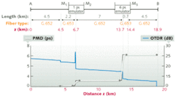
A prototype version of the instrument was proved both in lab experiments and in field trials with major network carrier companies.2 In one study, for an 18.9-km-long sample optical-fiber link containing fiber sections with PMD emulators positioned at 6.7 and 13.7 km, distributed-PMD values were correctly measured at 1 and 6 ps, respectively, with an uncertainty falling within the fundamental Gisin limit for PMD accuracy (see figure).
REFERENCE
- A. Ehrhardt et al., OFC/NFOEC 2009, paper NMB5, San Diego, CA (March 23, 2009).
About the Author

Gail Overton
Senior Editor (2004-2020)
Gail has more than 30 years of engineering, marketing, product management, and editorial experience in the photonics and optical communications industry. Before joining the staff at Laser Focus World in 2004, she held many product management and product marketing roles in the fiber-optics industry, most notably at Hughes (El Segundo, CA), GTE Labs (Waltham, MA), Corning (Corning, NY), Photon Kinetics (Beaverton, OR), and Newport Corporation (Irvine, CA). During her marketing career, Gail published articles in WDM Solutions and Sensors magazine and traveled internationally to conduct product and sales training. Gail received her BS degree in physics, with an emphasis in optics, from San Diego State University in San Diego, CA in May 1986.
