PRODUCT FOCUS: LASER-BEAM PROFILERS: How to select a beam-profile measurement system
A laser-beam profiling system consists of a detector or detector array, and analysis software used to capture, display, and record the spatial intensity profile or power density distribution of a laser beam. We talked with several beam-profiler manufacturers to find out what buyers need to know to buy the right product for their laser.
Who needs a laser-beam profiler? Designers and users who need to optimize the specifications of their laser or laser system, says Allen Cary, marketing manager at Photon (San Jose, CA). “That means just about anybody who’s trying to use a laser to do something, with the possible exception of a laser pointer,” says Cary. Typically, applications that require careful monitoring or measuring of the laser-beam width include laser-assisted in situ keratomileusis (LASIK) systems, laser printers, LIDAR systems, laser cutting, and nonlinear optics, to name just a few. Beam profilers are also used for pointing accuracy, for example, in pinpointing a beam’s location before it makes a cut.
If an application requires any finesse, then laser-beam profiling is a good idea. Manufacturers require beam profilers to deliver a consistent product and meet measurement standards. Beam profiling can greatly improve the efficiency of accuracy testing, alignment, and pointing in high-volume manufacturing and other applications, ultimately saving a lot of time and money.
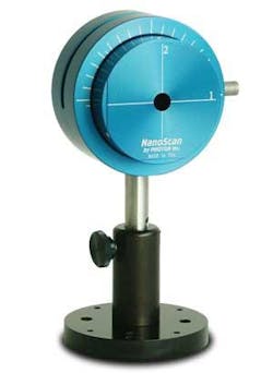
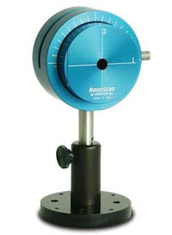
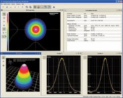
The two leading types of profiling systems are single-element “scanning-slit” systems and camera-based systems. Scanning-slit systems involve a slit typically about 5 µm in width and a single-element detector (see Fig. 1). Camera-based profilers use a camera as a detector array, typically a CCD or CMOS camera (see Fig. 2). A third profiling technique, scanning knife-edge, is generally used for only very small-diameter beams of less than 2 µm or so, says Andrew MacGregor, vice president of operations and support at DataRay (Bella Vista, CA).
The type of system you need depends on what you want to measure. Camera-based beam profilers generally allow “true” x-y mapping of the power density distribution along the length of the beam (in the z direction), a big advantage over scanning-type devices, which only provide integrated intensities in the x-y plane, says Egbert Krause, product line engineer for beam profilers at Thorlabs (Dachau, Germany). The advantage of slit-based systems is that they can handle higher-power lasers without attenuation. Beam attenuation typically requires optics like neutral-density filters or beam samplers placed in the beam path, which can adversely affect the profile unless care is taken.
Know your laser
When investigating beam profilers, start with what you know about your laser, including your wavelength, beamwidth, and power density. “If your laser is in the visible range, you’ve got a lot of options for the type of beam profiler,” says Cary at Photon. In the extreme-infrared (IR) and ultraviolet (UV), the technology becomes more expensive because of the technology, from indium gallium arsenide (InGaAs) cameras, to pyroelectric technology and microbolometer sensors (see Fig. 3).
The approximate spot size or width of your beam will further determine the type of profiler. Scanning-slit systems offer high resolution, and are ideal for small beams. Cameras work as long as the total beam fits within the sensor area. High-resolution cameras can have a pixel resolution of 4 µm, which may be all you need,” says Kevin Kirkham, product specialist, beam profiling, Ophir-Spiricon (Logan, UT). To figure out whether a standard silicon-based camera will suffice, typically cameras will require ten more pixels across the 1/e2 diameter of your beam.
Next, what is the power of your laser beam? Cameras are too sensitive for high-power beams, but slit-scanning systems can measure them directly. “Even tiny 1 mW diodes require attenuation of at least six orders of magnitude,” says Cary. If you’re interested in a true two-dimensional analysis of your beam, then you may need to use a CCD and deal with added attenuation.
Attenuation is one of the most challenging aspects of using a beam profiler. In almost every camera system, users must match the brightness of the laser to the camera sensitivity. “Sometimes you don’t have a long beam path, only a few centimeters,” says Kirkham, “so you have to reduce the intensity by 10, 12, even 15 orders of magnitude in a short path length.” Ophir-Spiricon’s LBS-300 attachment attenuates up to 99% of visible and IR beams with diameters up to 15 mm and powers from 10 mW to 400 W.
Finally, it matters whether your laser is continuous wave or pulsed. A pulse repetition rate of less than 1 to 2 kHz means using a CCD camera because scanning apertures aren’t effective at measuring it directly. If you can measure your beam directly, scanning-slit systems are best, such as in industrial manufacturing applications, where finessing attenuators would be too much fuss.
More than one manufacturer reports that customers often want a generic, one-size-fits-all laser-beam profiler, but there is no such thing. “You can’t measure both a 5 µm spot and a kilowatt laser with one profiler,” says Cary. Pyroelectric cameras are the most versatile, with the ability to analyze CW and pulsed high-power beams from x-ray to terahertz (although not all at once). However, the pyro-based profilers are pricey and they have limited sensitivity (the Ophir-Spirocon Pyrocam III saturates at 10 mJ/cm2).
What to measure?
The next trick is to decide which measurements you need, and the best way to measure them—“and that’s not trivial,” says MacGregor. (See www.laserfocusworld.com/articles/255504). Beamwidth can be defined at least five different ways: D4σ, 10/90 or 20/80 knife-edge, 1/e2, FWHM, and D86. The ISO standard defines D4σ, also called the second moment or 4sigma, as the diameter of the beam that is four times σ (the standard deviation from a Gaussian distribution). The 1/e2 beamwidth, also called 13.5%, is the distance across the beam inside the point at which the power drops to 13.5%. For a perfect Gaussian beam, defined theoretically as a TEM00 beam, the beamwidth for all those values is equal (see also www.laserfocusworld.com/articles/325693).
The beam-quality parameter, M2, measures the beam waist along the length of the beam, and is one of the most commonly desired measurements. “You might need to measure M2 if you are trying to meet the ISO beam-quality standard, which is necessary for laser manufacturers or users who want to check the laser spec,” says MacGregor. The perfect beam would be M2 = 1, which is a diffraction-limited waist, and theoretically the smallest beam possible. In theory, you can measure M2 with any type of beam profiler along a beam’s z axis. Both imaging and scanning-slit systems can achieve this measurement using software integration, moving z stages, multiple-plane slit systems, and wafer-thin cameras. DataRay offers the BladeCam, which at only 0.65 in. thick is billed as the “thinnest profiler in the known universe.”
“To obtain an M2 value,” says Kirkham, “the beam width measurements must be extremely accurate. Any errors propagate and skew the measurement.” A beam-propagation analyzer consists of a camera, software, and box with a lens that automatically translates the camera through the beam to show how the beam focuses through that lens. Beam propagation analyzers are offered by Coherent, DataRay, Ophir-Spiricon, Photon, and Thorlabs, among others.
Must one be an expert to use a laser-beam profiler? “A good manufacturer will help you select the correct system for your application, and help you come up to speed on how to use it,” says Kirkham. Some manufacturers may provide on-site support.
Final differentiators
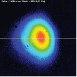
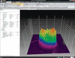
Because the calculations used in beam profilers are pretty standard, says Christian Johns, applications engineer at Thorlabs (Newton, NJ), the same measurements from two different manufacturer’s profilers should basically be the same. So when comparing similar products, the user interface is where you’ll notice differences that can help you choose a product you really like (see Fig. 4). Many manufacturers provide a free two-week demo of the software or the whole system as inventory allows. Having a rapport with the sales person should have some weight, and whether technical support will be easy to reach when you have questions.
Finally, it may come down to price. At the low end of the price range ($2500 to $3600) are slit-based scanning systems for visible and near-IR wavelengths. Single-element silicon-based sensors (such as CCD and CMOS) behind the slit are the least expensive. At the high end, systems for extreme-UV and IR applications, below 350 nm and above 1100 nm, where specialty sensors are required, can cost anywhere from $9500 to tens of thousands. High-end pyroelectric systems or custom systems that include high-resolution InGaAs cameras can cost as much as $22,000, according to Kirkham.
Editor’s note: This article is intended to provide some general guidelines to purchasers of beam-profiling systems. Laser Focus World does not endorse any specific products and because of space limitations we cannot include all suppliers and products. For additional information see the LFW Buyers’ Guide at www.laserfocusworld.com/directory.
About the Author
Valerie Coffey-Rosich
Contributing Editor
Valerie Coffey-Rosich is a freelance science and technology writer and editor and a contributing editor for Laser Focus World; she previously served as an Associate Technical Editor (2000-2003) and a Senior Technical Editor (2007-2008) for Laser Focus World.
Valerie holds a BS in physics from the University of Nevada, Reno, and an MA in astronomy from Boston University. She specializes in editing and writing about optics, photonics, astronomy, and physics in academic, reference, and business-to-business publications. In addition to Laser Focus World, her work has appeared online and in print for clients such as the American Institute of Physics, American Heritage Dictionary, BioPhotonics, Encyclopedia Britannica, EuroPhotonics, the Optical Society of America, Photonics Focus, Photonics Spectra, Sky & Telescope, and many others. She is based in Palm Springs, California.
