FIBER-OPTIC SENSING: Optical fibers detect tunnel-digging

Beneath the nine-mile border between Gaza and Egypt lie an estimated 300 makeshift tunnels, according to a Jan. 12 article in Asia Times. And Israel insists that without them, Hamas would not be able to stockpile rockets and mortars. Thus, permanent monitoring and destruction of these tunnels is a key sticking point in the struggle in the region.
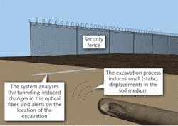
During the SPIE’s Defense, Security and Sensing Conference (April 13-17, Orlando, FL), researchers from the Technion-Israel Institute of Technology will present a method of detecting creation of just these kinds of tunnels and pinpointing their locations. Principal researchers Assaf Klar and Raphael Linker, both of the Technion Faculty of Civil and Environmental Engineering, say the system, based on fiber-optic cables, can locate even narrow tunnels at depths greater than 60 ft (see figure).
The research lays the groundwork for the initial stages of an underground fence based on Brillouin optical time-domain reflectometry (BOTDR) that makes it possible to measure fiber distortion along 15 miles using one device. The proposed system is based on “wavelet decomposition” of the continuous BOTDR signal, a process that breaks down the signal profile into simpler shapes, and then filters out noise. The signals that remain are then characterized by a neural network that has been trained to locate tunnels using computer simulation of tens of thousands of profiles, including disturbances (such as raindrops) not related to tunneling.
The system consists of conventional single-mode fiber optics, a BOTDR analyzer, and the computer software. Klar says the researchers considered two layout schemes for the fiber optics: one involved burying the fiber at a shallow depth along the border (“we call that the horizontal configuration,” he notes) and the other based on embedding the fiber in a vertical “mini-pile” (the vertical configuration).
Essentially, the BOTDR technology allows evaluation of Brillouin shift along an optical fiber, says Klar. (The portion of light traveling along a fiber that is backscattered experiences a frequency shift called the Brillouin shift). “As the Brillouin frequency shift is well correlated with the strain in the fiber, this information can be used to evaluate deformation in the soil,” he says.
He notes that the BOTDR does a combined time- and frequency-domain analysis, in which the time-domain information shows the location of measurement along the fiber, and the frequency analysis reveals the Brillouin frequency shift.
“Using the correlation between Brillouin shift and strain, the distortion of the fiber is measured,” Klar says. “The excavation process is associated with stress release in the soil which causes small static displacements in the soil. These displacements strain the fiber. The geotechnical aspects of how the tunnel induces displacement in the soil and how the fiber is strained due to those were all taken into account in the research.”
10 to 15 m detection range
Recommendations for spacing and depth of the fibers depend on variables such as soil condition and tunnel size. “However, we found that for soils (not rocks) we can detect very small tunnels even when the fiber is 10 to 15 m away from the tunnel,” says Klar. “This implies that if you use the vertical configuration and space the piles a distance of 20 m from each other, you have a very good coverage.”
While the BOTDR has a spatial resolution of about 1 m, the algorithm divides the continuous BOTDR signals into sections of 25 m, to which the wavelet decomposition and neural network classifications are applied. “The system first infers a tunnel being excavated within a section of 25 m. A detailed inspection of that section can probably pinpoint the tunnel to an accuracy of 2 to 3 m,” Klar explains.
The Technion researchers created the database of sound profiles themselves. “Geotechnology is my field of expertise,” says Klar, explaining that his group used continuum mechanics models, empirical relations, and discrete-element models–and conducted small-scale experiments in a centrifuge facility, which allows creation of similitude models. He says their goal was to create a broad range of input data, both for training the neural network and for testing its robustness against imperfect modeling. The system does extremely well in the robustness test, he reports, “probably because the tunnel excavation induces a very distinct–and wide–strain profile along the fiber, which the algorithm recognizes.”
Klar says his team has discussed the tradeoff between detection rate and false alarms with army officials, who have indicated a preference for missed detections over false positives. Klar’s presentation at the SPIE conference will include a comprehensive study on this tradeoff–but briefly, his group can produce zero false alarms with a detection rate of 70% (that is, 30% missed tunnel evacuations). Klar and his team have worked hard to understand the triggers for false positives, which include measurement error and surface activities that affect the fiber.
About the Author

Barbara Gefvert
Editor-in-Chief, BioOptics World (2008-2020)
Barbara G. Gefvert has been a science and technology editor and writer since 1987, and served as editor in chief on multiple publications, including Sensors magazine for nearly a decade.