OPTICS FOR SCANNING: Rapid scanning applications drive mirror design

DAVID BROWN
Mirrors used in scanning applications must meet dynamic flatness requirements while having low inertia and substantial heat dissipation–a daunting task. But this is just the beginning. Moving fast also means high bandwidth and requires stiffness in the entire moving system. To meet these requirements, optimal scanning requires integration of the mirror, its mounting, and the motor into a system called “M Cubed.” For successful integration, tradeoffs among M Cubed designs with respect to mirror substrate materials, mirror-to-motor attachments, inertia-minimizing structures, heat dissipation, and laser-induced damage threshold, must be carefully considered.
Mirror surfaces and substrates
In general, mirrors are used for scanning light from or onto a scene of interest (or both). The light is moved instead of the scene itself because the photons are lighter and can therefore be moved more quickly. However, the mirror or mirrors have substantial mass relative to the photons, and their mass is proportional to the cube of their aperture for a given set of mirror design rules. Hence, designers usually try to minimize the mirror aperture.
The legacy parameters of interest for mirror surfaces–flatness, reflectivity, surface quality, durability, and scatter (in about that order of importance)–continue to be germane. Today, however, it is increasingly the case that high power per se and high power density on the surface require tradeoffs.
Legacy substrate materials, with the exception of speculum metal, are all typically glasses. Although the hardness, elasticity, and amorphous structure of glasses continue to be desirable, they are also characterized by undesirable attributes such as low thermal conductivity, low coefficient of thermal expansion, and brittleness. Some glasses–quartz in particular–have a very low loss tangent, which means that vibrations are not well damped. High acceleration commands to a scanning system approach step functions in steepness. As a result, vibrational modes in elements of the system such as the mirror can be stimulated. Unless there is significant damping inherent in or coupled to the vibrating part, the system response is slowed. The ideal mirror substrate material would therefore have an amorphous or at least isotropic structure with no grain, high hardness, infinite stiffness, no mass, infinite thermal conductivity, and infinite loss tangent.
Dynamic stiffness–the tension modulus divided by the square of the density of the mirror material–is one of the two most critical measures of suitability for dynamic mirror use (see Fig. 1). For the majority of scanning applications, high laser powers combine with high accelerations with the result that candidates for mirror substrates should also have very high thermal conductivity. As a result, the product of dynamic stiffness and thermal conductivity is an excellent metric for selecting the best-performing mirror substrates (see Fig. 2).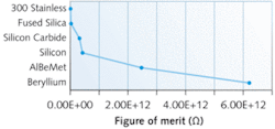
Coatings and laser-induced damage
The reflective coating is held to the substrate primarily by Van der Waals forces that are quite large, but of very small radius of action. The coating material (not always a metal) is very thin–on the order of 100 nm. So it has practically no transverse thermal conductivity no matter what the bulk thermal conductivity of the material might be. Therefore, the coating relies on the substrate to remove any power deposited in it.
While it may be nonintuitive, all coatings “leak” and therefore absorb considerable power. A mirror loaded with a specific laser power density of 500 W/cm2 and a reflectivity of 99.9% absorbs 0.5 W/cm2. Assuming aluminum for the coating material and a thickness of 100 nm, the volume of metal heated is 10-7 cm3 and the total specific heat of this metal is about 2 × 10-15 J/K. In the absence of adequate thermal conductivity to the substrate, the coating would simply evaporate.
In addition to sucking heat out of the reflective coating, the substrate must have a sufficiently close coefficient of thermal expansion so that the coating does not “bubble” away from the substrate. Silicon and silicon carbide have substantial thermal conductivity; however, their coefficients of thermal expansion are in the range of glasses. During the vacuum deposition process, the substrate is typically heated to about 200°C by the glow discharge used to clean it. When cooling to room temperature, the coating is put in compression if the coefficient of expansion of the substrate is slightly higher than that of the coating. Within limits, this effect is desirable because the stress is relieved when the mirror heats during use and most coating materials are metal/metal oxides whose tensile strength is low compared with their compressive strength. On the other hand, a large missmatch either way makes complex coatings crack or craze as soon as they come out of the chamber.
From this perspective, an aluminum/beryllium composition metal called AlBeMet is nearly ideal because it almost exactly matches the coefficients of aluminum and silver, the most widely used reflective base coatings. Nickel-plated beryllium is always satisfactory, because the nickel splits the differential between the beryllium and the reflective coating. Nickel is also desirable because it is easier to polish and exhibits very low scatter in the shorter-wavelength regions of the spectrum below about 532 nm.
Thermal conductivity of the substrate is also central to the problem of laser-induced damage from today’s Q-switched, continuous-wave (CW), and ultrafast Ti:sapphire and fiber lasers. At the high end of the power spectrum, it is safe to say that there is no optical element that will withstand the focused beam of any of these lasers. Best-practice naturally cooled mirrors should withstand 500 W/cm2 CW irradiance indefinitely. Forced convection cooling increases the power handling by perhaps a factor of five, depending on the geometry of the cooling and degree to which the servo will tolerate the increased mechanical noise.
A mirror designed for 500 W/cm2 specific power density will work successfully with Q-switched and other long-pulse lasers as long as the average power is at or below 500 W/cm2 and the irradiance is below 1, where 1 is the product of the peak specific power in W/cm2 and the interaction time in seconds. The situation may be different for ultrafast lasers in the pico- to femtosecond range. Until reliable data are available, it is probably best to keep peak intensity on the mirrors below 1010 W/cm2 when pulse lengths are under 10-12 seconds.
Substrate structural design
The simple plane-parallel slab with the corners cut off is the least expensive substrate structure. It is also the design with the highest inertia. The precise shape of an optimal mirror profile will vary somewhat from application to application, but in general it is pyramidal with a central flat and tapering wings. Inertia of the mirrors can be further reduced by drilling or forming holes parallel to the reflective surface of the wings.
The perimeter of the mirror can either be a closely circumscribed polygon or an ellipse. It is essential that the mirror be stiff enough that the stresses imposed by the coating layers do not bend it, irrespective of the requirements of system bandwidth. If the coating bends the mirror, then it will change curvature with temperature in an effect called thermal lensing, which changes the angle of convergence of the beam and thus the spot diameter.
A typical high-performance scanning mirror design in beryllium has an aperture of 50 mm, is designed for a peak-to-peak optical (PtPO) scan angle of 40°, is flat to better than 1/4λ at 633 nm, has a moment of inertia less than 76 gm/cm2, and is nickel plated all over (see Fig. 3). It will support laser notch coatings at all the popular laser wavelengths and will just barely handle 10 kW with forced convection cooling. It has a first resonance in torsion of 4636 Hz to support a system closed-loop bandwidth in excess of 2 kHz. This is an example of a best-practice mirror design whose combined desirable properties cannot be approached in any other known material.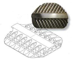
Mounting and system design
For the most efficient transfer of power from a motor to its load, the inertia of the motor and load should be matched. In other words, the inertia of the motor rotor should be half of the total inertia. This leads to the conclusion that every scanning-system design should proceed from the mirror to the motor and not the reverse. Where this is possible, the best solution is for the mirror to have an integral stem (or a suitable rigidly integrated extension) that passes through the front bearing and attaches to the magnet (or coil in a moving-coil design). This minimizes the length of the output shaft, usually the major contributor to lack of stiffness in the motor.
It is necessary to attach the mirror to the motor in such a way that the center of mass of the mirror is on the axis of rotation within quite close limits (otherwise it will wobble as the rotating structure attempts to rotate around the actual line between the mass centers) and to transmit enough torque without slipping to accelerate the mirror to the limits imposed by the bandwidth of the system. A simple robust solution is to fasten the mirror into a slot in the shaft by means of epoxy. Assuming that the shaft diameter is adequate, this approach can be almost as stiff as the integral-stem ideal.
The literature is full of clamp-on mirror mounts of various descriptions, some integral with the mirror. All these examples require some extension of the motor shaft, and most clamping mechanisms fail to clamp tightly unless supplemented by a bonding agent. The approach used by Cambridge Technology is a method derived from the machine-tool industry, which faces similar issues. Machine-tool spindles universally have hollow tapered axial cavities into which the tool is inserted. The tool has a mating male taper. This system is capable of highly concentric, very low-tilt location of replaceable tools, a substantial degree of torque transmission, and, of course, infinite adjustability of the relative rotational position of the spindle and the tool. Since the motor output shaft is hollow, the mirror male taper occupies space inside the motor shaft, thus maintaining minimum shaft length. When assembled, the motor shaft and mirror stub become essentially one piece, preserving the maximum stiffness of the shaft.
With these best-practice materials and techniques, scanning-mirror systems with closed-loop bandwidths in excess of 2 kHz moving 10 kW laser beams are now practical.
David Brown is chief scientist at Cambridge Technology, 25 Hartwell Ave., Lexington, MA; e-mail: [email protected]; www.cambridgetechnology.com.