PRODUCT FOCUS: POWER SUPPLIES: Laser-diode power-supply basics: performance depends on specification
Diode lasers have become the laser of choice in many optoelectronic systems because of their versatility, stability, and relatively low cost. The power supplies for laser-diode systems, called laser-diode drivers or controllers, are an important prerequisite that, ironically, seem to get the least consideration by designers and consumers. Manufacturers offer a mind-boggling array of drivers and controllers for bench-top laser-diode systems, each with numerous features and specifications. Buyers must consider a number of important features of the instruments when making their choice.
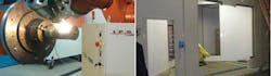
The terms laser-diode driver and laser-diode controller are often used interchangeably. Many manufacturers, however, designate the term “driver” to refer to just the current source (see Fig. 1), while “controller” refers to an all-in-one current source and temperature-control mechanism, typically a thermoelectric cooler (TEC). For researchers whose applications require critical temperature stability, a controller is required (see Fig. 2). Some firms describe drivers/controllers as “programmable” as opposed to “fixed”—the latter being the generic, fist-size commodity power supplies used for everything from laptop computers to printers. The term “research-grade” or “bench-top” means the drivers and controllers are designed for use on an optical bench in a lab, offering more features at a higher price.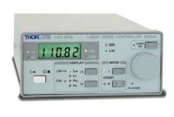
Laser diodes are expensive and have delicate electronic loads that often operate at voltages and currents close to their destructive limits. According to Matt Kowitt, project manager at Stanford Research Systems (SRS; Sunnyvale, CA), the powering electronics that operate diodes must be carefully designed to avoid overvoltage, overcurrent, and similar glitches that can quickly result in the destruction of a thousand-dollar diode that may have taken months to characterize. Larry Johnson, founder and chief executive officer of ILX Lightwave (Bozeman, MT), explains why his company specializes exclusively in laser-diode power supplies: “As a developer of fiber-optic sensors, I believed the two most urgent things in the lab were how do I protect my expensive laser, and how do I stabilize it?”
Know your diode
The first priority when purchasing a laser-diode driver/controller for bench-top applications is to know your diode’s current requirements and operating voltage. The diode specification sheet lists the required operating current, the maximum current it can take (also called absolute current or current limit), and voltage range. Typical diodes operate around 2 V, whether they’re low or high power, according to Ramin Ershadi, product manager, Photonics Instruments, at Newport (Irvine, CA). Blue laser diodes might require as much as 10 V. Standard laser drivers/controllers typically provide either 5 or 7 V. For R&D applications, look for a driver that offers the lowest appropriate voltage for your diode, and that has settings for maximum drive current and “compliance voltage” to prevent damage to your laser.
Features that maintain the stability of current and voltage are crucial. Some controllers have a photodiode feedback mechanism built in for monitoring the output power, says Ershadi. The photodiode triggers the system to increase or decrease the current if the output power changes, even if the input current stays the same. For example, a 5 mW output laser with such a photodiode feedback mechanism would have a current variation of less than 1%, depending on the laser and the driver.
The next consideration is to choose between CW, pulsed, or modulated modes of operation. “The majority of applications are CW,” says Ershadi. “Telecom ‘apps’ are usually modulated. Apps that limit delivered energy, such as R&D of diode fabrication or fluorescence measurements, might require pulsing.” Some manufacturers, such as SRS, specialize only in CW drivers and controllers.
Noise, noise, noise
One crucial step is to balance the required current range with the noise it produces. At higher currents, the associated noise increases (as does cost). Noise can come from spikes or transients generated from an external line or improper grounding, or internal noise from the electronics and circuitry. “Grounding yourself is very important before you even reach to plug in your system,” says Ershadi. “A static shock can generate a pulse of up to 2000 V that can toast your laser diode before you even open the package.”
Noise in laser-diode drivers is typically specified as random noise or “ripple,” measured as a root-mean-square (rms) current over a specified bandwidth. Generally, a maximum current noise value should be in the single digits or less in units of microamperes (µA; see table). Internal circuitry in laser-diode drivers often provides protection from spikes that occur, for example, when you turn on another device plugged into the same power strip.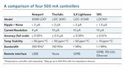
How much noise a system can tolerate depends on the application—for example, a pumping application tolerates more noise than a demanding physics experiment with extremely high resolution. Another key to low noise, says Kowitt of SRS, is a linear power supply, rather than a switch-mode power supply. A switching-mode system can produce high-frequency noise in the internal circuits.
Temperature
For controllers, an important specification is the temperature coefficient of the TEC. Temperature variation impacts the wavelength stability of a laser, and can cause mode-hopping. For a laser operating at 635.2 nm, the wavelength changes 0.1 nm for every 1°C change in ambient room temperature or temperature control. Applications that are wavelength-dependent, such as absorption research in biophotonics, are particularly vulnerable to temperature variations. Some controllers provide automatic temperature stability with the push a button.
Four-wire voltage sensing is a feature useful in high-current applications that require critical accuracy in the TEC measurements. Wires supplying current to the TEC experience a slight voltage drop when they are tapped for voltage monitoring. In a four-wire measurement system, the two current-supply wires are separate from the two voltage-monitoring wires., separate wires are used for current supply and voltage measurement. This feature prevents intermittent surges to the TEC that could destroy the diode by overvoltage.
A well-designed front panel should have an independent display on the controller separate from the monitor display–one for operating temperature and one for current. In this way, a change of either the input temperature or current on the monitor display will appear independent of the value on the read-out display. Some controllers have three displays—one dedicated to the TEC temperature measurement, a second larger display that shows the measured current going through the laser, and the third display shows the target values entered by the user.
Other features
John Breickner, product manager, TDK Lambda Americas (Neptune, NJ), notes that a consideration often overlooked during the design phase of a laser-diode system is whether the components are compliant with the Restriction of Hazardous Substances (RoHS) directive mandated in the European Union. Laser systems destined to be sold in Europe or Japan, or to “green-conscious” companies everywhere, require certification of RoHS compliance (see www.rohsguide.com), which restricts the use of six hazardous materials found in electrical products.
Safety features can prevent a laser from turning on when it’s not supposed to. An interlock as part of the optical system consists of two pins that must be electrically joined to enable the laser to power on. If two people are working in one lab, the interlock prevents one of them from starting the laser if, for example, the safety cover on the optical bench is open. With diode lasers, scientists often must cobble together a custom system. A laser-diode TEC lockout feature is another option that disables the laser when a TEC controller is not active.
Other features to consider include an adjustable bias-voltage controller on the monitor photodiode, and on-the-fly switching between constant current and constant optical power, also called bumpless transfer or live switching. For demanding applications, laser-diode controllers often include remote programming and analog modulation. A multichannel controller offers several independent channels of current source, for driving more than one diode at a time, as in biophotonics or manufacturing quality assurance.
To find a comprehensive list of suppliers and additional information, visit the Laser Focus World Buyers Guide at https://www.laserfocusworld.com/directory.
Editor’s note: The “Product Focus” series is intended to provide a broad overview of the product types discussed. Laser Focus World does not endorse or recommend any of the products mentioned in this article.
About the Author

Valerie Coffey-Rosich
Contributing Editor
Valerie Coffey-Rosich is a freelance science and technology writer and editor and a contributing editor for Laser Focus World; she previously served as an Associate Technical Editor (2000-2003) and a Senior Technical Editor (2007-2008) for Laser Focus World.
Valerie holds a BS in physics from the University of Nevada, Reno, and an MA in astronomy from Boston University. She specializes in editing and writing about optics, photonics, astronomy, and physics in academic, reference, and business-to-business publications. In addition to Laser Focus World, her work has appeared online and in print for clients such as the American Institute of Physics, American Heritage Dictionary, BioPhotonics, Encyclopedia Britannica, EuroPhotonics, the Optical Society of America, Photonics Focus, Photonics Spectra, Sky & Telescope, and many others. She is based in Palm Springs, California.