OPTICAL TRAPPING: Zone-plate optical tweezer can integrate with microfluidics
The forces exerted by tightly focused laser beams can create optical tweezers for the purpose of manipulating small particles (see www.laserfocusworld.com/articles/302490 and 318548). However, the short working distances (less than 200 µm), relatively large physical size (30 mm barrel diameter and 60 mm barrel length), and high cost of the precision microscope lenses used in conventional tweezer designs make it difficult to integrate them into microfluidic chip systems. However, researchers at Harvard University (Cambridge, MA) have devised a new optical tweezer that traps particles in a microfabricated Fresnel zone plate, eliminating the need for bulky and expensive microscope lenses.1
Designed to be used at the glass/water interface of a sample cell, the zone-plate optical tweezer allows the use of a 100 µm diameter, short-focal-length lens (less than 8 µm) with an effective numerical aperture of 1.31. The zone plate is fabricated on a glass slide coated with indium tin oxide to prevent charging during lithography. A polymethylmethacrylate (PMMA) layer is spun on the substrate and exposed by e-beam lithography. Gold is then evaporated onto the PMMA to a thickness of 50 nm, with a thin layer of chrome used for adhesion. A lift-off process then yields the zone-plate pattern consisting of concentric gold rings and dark regions (glass) where the gold has been removed.
Experimental setup
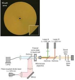
The particular zone plate used in the experimental setup has a period of 745 nm at the outermost ring, and was designed for use with a free-space illumination wavelength of 976 nm (see figure). The 100-µm-diameter zone plate is illuminated by a fiber-coupled, 976 nm laser diode that is collimated to a diameter of 180 µm to overfill the zone-plate aperture. The focused output from the zone plate produces a focal-spot size with a full-width half-maximum value of 302 nm along the x-axis, and 473 nm along the y-axis, the polarization direction of the input beam.
A sample cell is formed by sandwiching a layer of water between the zone-plate substrate and a glass coverslip. A helium-neon laser and a microscope objective are used to form a conventional optical trap to load 2-µm-diameter polystyrene fluorescent beads into the area near the Fresnel-zone-plate trap, speeding up the time it would normally take for a particle to diffuse into the trap. A green laser is used to excite fluorescence in the beads, and low-pass and bandpass filters are used to remove the 976, 633, and 532 nm wavelengths to isolate the fluorescence wavelength onto a charge-coupled-device (CCD) camera to analyze the movement and trapping of the particles by the Fresnel zone plate.
Once the zone-plate trap is loaded with a particle, the helium-neon laser is turned off and the green laser is turned on. To determine the trapping stiffness, a measure of how well the trap holds onto a particle, movies of trapped beads were acquired at 30 Hz to capture bead motion as a function of time and as a function of the 976 nm laser power, which ranged from 40 to 140 mW. Analysis of the image data showed that the zone plate’s current stiffness value (approximately 0.03 pN/µm mW) compared well to high-performance traps, and could be increased by a factor of 4 by not overfilling the zone plate. In addition, the stiffness could be increased by another factor of 4 by using a π phase zone plate.
The much smaller cross section, thickness, weight, and small working distance resulting from using a zone plate as the focusing optic in this optical-tweezer scenario allows this tweezer to be embedded deep inside microfluidic chambers. In addition, particles can be released simply by moving the zone plate away from the illumination source.
Future work will concentrate on creating arrays of tweezers. “We plan on fabricating arrays of zone plates that trap a large number of particles,” says Ethan Schonbrun, Harvard postdoctoral fellow. “Each particle can probe in a different location of the microfluidic cell and in this way, different properties of the fluidic channel—such as flow velocity, viscosity, and temperature—can be spatially mapped by observing the trapped particles.”
REFERENCE
1. E. Schonbrun, C. Rinzler, and K.B. Crozier, Appl. Phys. Lett. 92, 071112 (2008).
About the Author

Gail Overton
Gail Overton served as a senior editor for Laser Focus World from 2004 through 2020. She has more than 30 years of engineering, marketing, product management, and editorial experience in the photonics and optical communications industry. Before joining the staff at Laser Focus World, she held many product management and product marketing roles in the fiber-optics industry, most notably at Hughes (El Segundo, CA), GTE Labs (Waltham, MA), Corning (Corning, NY), Photon Kinetics (Beaverton, OR), and Newport Corporation (Irvine, CA). During her marketing career, Gail published articles in WDM Solutions and Sensors magazine and traveled internationally to conduct product and sales training. Gail received her BS degree in physics, with an emphasis in optics, from San Diego State University in San Diego, CA in May 1986.