SPECIALTY FIBERS: Novel process eases production of hollow-core fiber
RODRIGO AMEZCUA CORREA and JONATHAN KNIGHT
Optical fibers are typically formed from two glasses: the first, with a higher refractive index, runs down the middle of the fiber, forming the core in which light is trapped; the second, lower-index glass, surrounds the first, protecting the core and forming what is known as the cladding of the fiber. The inner glass must have a higher refractive index than the outer because, as we all learned in high school, light can then be trapped in the core by total internal reflection (TIR). Those same school textbooks also taught us that TIR is the means by which all optical fibers work. But that is not the whole story. The fact is, it is impossible to trap light in a hollow core using TIR. Instead, it can only be done by surrounding the hollow core with a number of smaller holes, arranged in a periodic matrix, to form a photonic-bandgap material.
But why trap light in a hollow core at all? The development of conventional optical fibers to the current state of the art represents a truly fantastic achievement. We use them every day when making telephone calls, replying to e-mails or using the Internet. Increasingly, they are used in medicine, machining and welding, structural sensing, biological research, and a host of other fields. So why change them?
Although their performance is in many ways superb, there are some things that conventional fibers simply cannot do. The limiting properties of conventional fibers are dictated by the properties of the glass from which the core is formed and through which the light must pass. Although fiber designs are flexible, the properties of the material from which they are formed—usually silica glass chosen for its incredible transparency—are not. Hence, fibers with a hollow core can easily outperform conventional fibers for certain applications. As a result, hollow-core photonic-bandgap fibers have been developed over the past decade from the initial radical concept to a high-performance product.
How to make them … even better
In the “best” hollow-core fibers—those with lowest attenuation—special attention has been paid to the periodic structure forming the photonic-bandgap cladding and to the interface between this cladding and the hollow core. Ideally, the hollow core would be formed so as to introduce a single core-localized photonic state within the cladding bandgap. Light introduced into this state would then be unable to escape from the core through the surrounding cladding material. In principle, the core can be simply formed by omitting one or more entire unit cells from the photonic crystal, leaving a void. To see why this has historically been difficult, one needs to understand something of the fabrication process used to form these fibers.
The fabrication process involves stacking several hundred fused-silica capillaries together, inserting the stack into a tube, and drawing it down to fiber (see Fig. 1). The tubes fuse together, and their bores become the tiny holes needed in the final fiber. To obtain the required bandgap structure in the cladding, the tubes must have thin walls. However, the use of thin-walled capillaries means that the cladding structure does not contain enough glass at the vertices of the close-packed array of holes, so previous workers have painstakingly inserted additional material (in the form of fine fibers) into the stack at each interstitial point. The spaces between the capillaries were then evacuated during the fiber draw to collapse the vestigial air holes. Simply omitting several unit cells to form the hollow core then becomes difficult, because the vacuum used to remove the vestigial air holes would also cause the core to collapse.
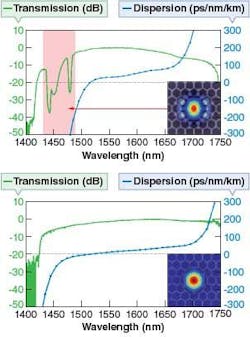
This difficulty has traditionally been addressed by inserting an extra, larger tube into the stack to define the core. This tube replaces the several capillaries omitted during the stack, preventing the cladding capillaries from falling into the core and protecting the core from the vacuum. However, it has other, less beneficial, effects. In particular, the addition of the extra glass around the core leads to the introduction of unwanted guided modes into the bandgap.1 These “surface” modes exist in the same spectral range as the core-guided “air” mode, but have far higher dispersion due to their large overlap with the glass. They interact with the air mode in some wavelength ranges, greatly increasing the attenuation and dispersion of the air mode and reducing the usable bandwidth of the fiber.To overcome this problem, we recently demonstrated a far simpler fabrication process.2 In the new process, the capillaries are still stacked together, but we use thicker-walled capillaries than we need, and inflate the entire structure during fiber drawing. The inflation helps to close the interstitial air holes—which no longer have to be filled with fibers—and makes it possible to form a core without adding the core tube. Instead, the core formed by omitting seven capillaries from the stack is filled at each end using much shorter capillaries, remaining unsupported in the middle. The omission of the core tube and the interstitial fibers results in a faster procedure, reducing the time it takes to fabricate a preform and draw the first working fibers to a single day, rather than around a week.
Better performance
Remarkably, the silica glass wall around the hollow core in the new fibers is only about 100 nm thinner than previously. This tiny structural change, however, completely removes surface modes from the bandgap region and the performance of the fibers is thus improved in several ways. Most obviously, the range of wavelengths that can be transmitted with low attenuation is increased (see Fig. 2). As a result of the increased bandwidth, the rate that the properties of the core mode change with wavelength is decreased, so the group velocity dispersion and the dispersion slope are both reduced. The lowest optical attenuation is comparable to (actually, slightly better than) the previous state-of-the-art for similar fibers with a seven-cell core.
The broader bandwidth reduces the engineering constraints on some applications, and will enable others for the first time. For example, the broader wavelength range makes it easier to satisfy other specifications—such as the mode-field diameter, or the external-fiber diameter—at the same time as having low-attenuation guidance at a specific wavelength of interest. This makes it far easier to integrate hollow-core fibers into all-fiber systems by facilitating compatibility with conventional fibers.
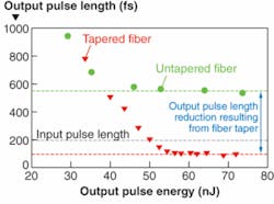
For developing applications in nonlinear microscopy, the ability of a fiber to deliver several laser wavelengths simultaneously is critical, while being able to collect the resultant optical signal at yet other wavelengths will mean that fiber-enabled nonlinear imaging moves a step closer. Use of hollow-core fibers for delivery and manipulation of femtosecond pulses as solitons is currently limited by the variation of the dispersion with wavelength.3 The new fibers have a linear dispersion over a wide wavelength range, making it possible to deliver high-power femtosecond pulses as solitons over a wider range of pulse energies than previously possible. The reduced dispersion slope means that not only will solitons propagate more stably than before, but they can also be used at lower values of the fiber dispersion without being catastrophically close to the zero-dispersion wavelength, allowing propagation of lower-energy solitons than previously.The soliton self-frequency shift will, however, still result in the central wavelength lengthening as the solitons propagate along the fiber. So they will gradually move to spectral regions with greater dispersion. This greater dispersion, coupled with the intrinsic attenuation of the fiber, mean that the solitons will lengthen as they propagate. This pulse spreading can be compensated by decreasing the fiber dispersion along its length. This is simply done: as shown in Fig. 2, a simple variation in the overall structure of the fiber—by tapering the outer diameter to a larger size—will cause the GVD at a specific wavelength to decrease. The same effect has been demonstrated in conventional fibers, but they can never support solitons with such high energies, nor can they have the required anomalous dispersion at wavelengths shorter than around 1300 nm. A tapered hollow-core fiber has been used to efficiently compress and deliver amplified femtosecond pulses from a mode-locked fiber laser as solitons over several meters of fiber (see Fig. 3).4 The transform-limited hollow-core fiber output has been shown to be an efficient pump source for frequency-doubling, resulting in 60% conversion efficiency to the green.5
The recent developments in hollow-core photonic bandgap fiber technology make their production far easier and cheaper as well as bringing them close to one of their natural limits. For the first time, core-confined guidance with low attenuation is possible over the full bandgap of the photonic crystal cladding. Further improvements—to cladding design and to the core surround—surely lie ahead, but for now, hollow-core fibers with state-of-the-art performance are more readily available than ever before.
ACKNOWLEDGMENT
This work was supported in part by the EU Framework 6 project “NextGenPCF.”
REFERENCES
1. J. West et al., Opt. Express 12, 1485 (2004).
2. R. Amezcua-Correa et al., Opt. Express 16, 1142 (2008).
3. D.G. Ouzounov et al., Science 301, 1702 (2003)
4. F. Gérôme et al., Opt. Express 15, 7126 (2007)
5. F. Gérôme et al., Opt. Express 16, 2381 (2008)
Tell us what you think about this article. Send an e-mail to [email protected].
RODRIGO AMEZCUA CORREA is a postdoctoral researcher and JONATHAN KNIGHT is professor and director at the Centre for Photonics and Photonic Materials at the University of Bath. They are at the Department of Physics, University of Bath, Claverton Down, Bath, BA2 7AY, England; e-mail: [email protected]; www.bath.ac.uk/physics/groups/cppm/index.php.


