Superresolution Optics: Optical imaging resolves beyond the diffraction limit

VICENTE MICÓ SERRANO, JAVIER GARCÍA MONREAL, AND ZEEV ZALESKY
Many attempts have made to improve the resolving power of optical imaging systems since Ernst Abbe discovered at the end of the 19th century that the resolution of an imaging system is limited by diffraction. When applied to the field of microscopy, Abbe’s work concludes that conventional high-resolution microscopy requires high-numerical-aperture (NA) microscope objectives. However, high-NA imaging lenses are costly and not always practical. A 1.4 NA oil-immersion objective lens, for instance, has a typical working distance of several hundred microns and a highly reduced field of view, which limits the physical proximity of the lens to a sample as well as the types of specimens that can be imaged.
Diffraction theory states that an optical imaging system acts as a low-bandpass filter selecting the low spatial frequencies of an object’s spectrum. In other words, one can say that the imaging system has a transfer function that multiplies the overall frequency content of the object and introduces a physical limitation by posing a cut-off frequency in the Fourier domain and, as a consequence, limits the resolving power. This cut-off frequency value is defined by the NA of the imaging lens and limits the maximum possible resolution to a value of λ/2 for air-immersion optical systems and incoherent illumination, where λ is the illumination wavelength.
To overcome this limitation, information theory provides the necessary theoretical background by establishing an invariance theorem that states the information capacity (given by the number of degrees of freedom) of an imaging system remains constant. Thus, provided that the input object belongs to a restricted class, it is possible to extend the spatial bandwidth (or any other desired parameter) by encoding-decoding additional spatial-frequency information onto the independent (unused) parameter(s) of the imaging system in such a way that it will then pass through the limited system aperture. This is the fundamental principle underlying all superresolution schemes.
An example of such object classification using a priori information is an object that is approximately independent of one variable, such as time, polarization, wavelength, dimensions, or dynamic range. For instance, because of the finite size of the system’s aperture, some of the spatial-frequency signal information will be lost. If it is known that the signal information is monochromatic, it is possible to convert part of the spatial information into wavelength information in such a way that the aperture of the system is synthetically expanded, which ultimately improves resolution.
Motivation
In this context, superresolution techniques aim to improve spatial resolution without changing the physical properties of the optical system. These techniques can be understood as the generation of a synthetic aperture (SA) that increases the frequency coverage of the optical system beyond the limit defined by its cut-off frequency; that is, beyond its physical limited aperture.
But the question is: which techniques provide synthetic-aperture super-resolution? By definition, such methods imply the generation of a synthetic aperture that permits high-resolution images using low-NA lenses. In microscopy, low-NA microscope objectives have attractive advantages such as long working distance, large field of view, large depth of focus, and relatively low cost compared to higher-NA microscopes objectives. So, besides the fact that high-NA lenses are not useful for some applications, low-NA microscope lenses obtain only questionable benefit from the superresolution techniques. For those applications that present conflicting requirements for high-resolution imaging over large fields of view at a large working distance from the sample, synthetic-aperture superresolution techniques can be the key to success.
Mask inspection in the semiconductor industry and microscopic biological applications are two potential applications for synthetic-aperture superresolution techniques. In the semiconductor industry, the decreasing dimensions of mask features require higher-resolution optics, while the need for increasing inspection speed demands that the imaging optics must maintain a long working distance from the mask to provide a large field of view. In biology, many samples have protective pellicles mounted above them or are hard to access. In these cases, it is essential to have a long working distance to image the sample, which decreases resolution in the final image. Once again, synthetic-aperture superresolution techniques provide a solution.
Many approaches have been proposed to achieve superresolution effects.1 In particular, far-field-imaging superresolution techniques are attractive in applied-optics disciplines such as digital microscopy, optical lithography, and information transmission. However, samples that are temporally restricted require exploitation of the temporal degree of freedom.
Time multiplexing
In general, superresolution effects are achieved in at least two basic steps. First, we encode the object’s spectrum to divert the higher spatial-frequency content through the imaging-lens aperture. The second stage is to recover and correctly reassemble the frequency content transmitted in the encoding stage. In some cases, the decoding procedure may not enable restoration of new bandpass frequency content to its original position in the spectrum. If so, a third post-processing stage allows final superresolved imaging. Because digital sensors are a relatively modern development, historically superresolution involves only the first two stages.
The encoding stage typically uses external elements such as diffraction gratings, prisms, or special illumination methods that allow the transmission of a wider object’s spectrum through the limited system aperture. The classical way to accomplish this encoding is to use diffraction gratings as the encoding mask. Other methods involve optically generated gratings that can increase the lateral resolution beyond the diffraction limit in conventional microscopy imaging. Optically generated gratings are also used in fluorescence microscopy, using both structured illumination and optical nonlinearity in the pattern excitation processes.
All of these methods have the same underlying purpose: the diffraction grating diverts the on-axis high-frequency-diffracted bands of the object’s spectrum, and passes spatial-frequency information through the system aperture. The rest of the information remains to be recovered. This is the aim of the decoding stage, recovering each frequency band and properly placing it in its original position in the object’s spectrum
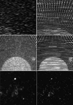
Another way to achieve time-multiplexing superresolution is the use of speckle patterns instead of gratings.2 Speckle patterns can be understood as a continuous case compared to the discrete case of a diffraction grating. Simply coding and decoding the input and the output, respectively, with a given speckle pattern enables superresolution in two dimensions. A speckle-pattern projection method greatly reduces complexity compared to the projection systems used in structured illumination (see Fig. 1).
Coherence coding also facilitates time-multiplexing superresolution in both spatial and temporal ways. In spatial coherence coding, the mutual intensity function of the illumination beam is used to code spatial information in an analogous way to time multiplexing. The information is multiplexed in time slots separated by an interval of at least the coherence time of the illumination beam.3 Instead of generating diverse distributions, each one with different transverse coherence functions, the longitudinal axis is used to code the transverse spatial information in the temporal coherence coding by using incoherent light interferometry.4 After that, interferometric image-plane recording and a digital post-processing stage allow the needed decoding to achieve the superresolution effect.
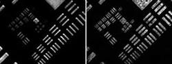
An analogy of tilted beams helps explain coherence coding. The key idea is the equivalence between a diffraction grating and a set of tilted beams (on-axis and off-axis beams) with the same propagation angles as those diffracted by the grating. Thus, the off-axis illumination is used to downshift the high-frequency components of the object’s spectrum to low-frequency ones, allowing its passage through the system aperture. In that sense, the encoding stage is defined as a set of illumination beams having different incidence angles (on-axis and off-axis). When these tilted beams impinge upon the input object, each of them produces a frequency shift in the object’s spectrum according to the beam propagation angle. Once again, a decoding stage and in most cases a digital post-processing stage restore each diffracted band according to its original diffraction angle (see Fig. 2).
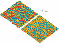
Over the last few years, time multiplexing has been combined with digital holography to recover the complex amplitude distribution of the sample under test. In particular, one interesting application for this interferometric imaging is microscopy, in which synthetic-aperture generation permits the extraction of medium- and high-resolution images using low-NA microscope lenses.5, 6 Much like the grating and speckle-pattern processes, this technique also directs off-axis illumination onto the object and enables the transmission of high-frequency bands through a limited system aperture. Using holographic image-plane recording, a digital filtering and relocation process generates a synthetic aperture and restores each transmitted frequency band to its original position in the object’s spectrum. Finally, a simple Fourier transformation of the information contained in the sythetic aperture creates a superresolved image (see Fig. 3).
REFERENCES
1. Z. Zalevsky and D. Mendlovic, Optical Super Resolution, Springer (2002).
2. J. García, et al., Optics Express 13, 6073 (2005).
3. Z. Zalevsky, et al., Optics Lett. 30, 2837 (2005).
4. V. Micó, et al., Optics Lett. 32, 736 (2007).
5. V. Micó, et al., Optics Express 14, 5168 (2006).
6. V. Micó, et al., Optics Comm., 276, 209 (2007).
Tell us what you think about this article. Send an e-mail to [email protected].
VICENTE MICÓ SERRANO is a Ph.D. researcher and optical-design unit manager at the Optical Engineering Department of AIDO, Technological Institute of Optics, Colour and Imaging, Nicolás Copérnico, 7-13 Parc Tecnològic, 46980 Paterna, Spain; JAVIER GARCIA MONREAL is professor of optics and at the University of Valencia, 46100 Burjassot, Valencia, Spain; and ZEEV ZALESKY is a senior lecturer at the School of Engineering, Bar-Ilan University, Ramat-Gan, 52900 Israel, and head of the nanophotonic section at the Nano Technology Research Center of Bar-Ilan University; e-mail: [email protected]; www.uv.es/gpoei.