MEDICAL OCT: Ultra-high-resolution optical coherence tomography gets adaptive-optic ‘glasses’
ROBERT J. ZAWADZKI, BARRY CENSE, STEVEN M. JONES, SCOT S. OLIVIER, DONALD T. MILLER, AND JOHN S. WERNER
Adaptive-optics techniques, which are well known for correcting Earth-based atmospheric effects in astronomical images, are finding new practical application on a smaller scale for retinal imaging.
In only 15 years, optical coherence tomography (OCT) has revolutionized treatment and monitoring of retinal diseases.1 Its superb axial resolution, independent from lateral resolution, allows precise in vivo visualization and characterization of all the main cellular layers in the human retina. Unfortunately, as in other imaging techniques, lateral resolution and therefore the quality of OCT imaging is reduced by imperfections in the eye’s optics. Incorporation of wavefront correctors in various retinal imaging systems, including OCT, can improve lateral resolution.2
While adaptive optics (AO) reduces the degrading impact of ocular aberrations, full compensation of both low- and high-order aberrations of the eye has not been achieved. This is a limiting factor for AO-OCT systems in clinical settings. Standard methods of refractive vision correction, such as placement of trial lenses in front of the eye, adversely affect the implementation of OCT imaging. As a possible solution to this problem, we recently reported a novel “trial-lens-free” AO design that cascades two deformable mirrors3 for the purpose of extending the correction range (amplitude) beyond that of systems using a single wavefront corrector.4, 5
In a previous AO-OCT imaging system, we attained an axial resolution of approximately 6.5 µm with a broadband light source. Now, we have developed a new generation of adaptive-optics ultra-high-resolution (UHR) OCT, (AO-UHR-OCT) instrumentation that combines an ultrabroadband spectral light source and a custom achromatizing element to increase measured axial resolution to approximately 3.5 µm, without reduction in lateral resolution and image quality.
New AO-UHR-OCT instrument
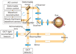
Like the previous device, the new AO-UHR-OCT instrument uses an AO system in the spectral/Fourier-domain OCT sample arm to facilitate correction of a patient’s ocular aberrations. The detection channel of the OCT spectrometer acquires spectral fringes of light back-scattered from the retina combined with light from the reference arm. The OCT-control unit drives vertical and horizontal scanners with programmable scanning patterns (maximum of 4° field of view), and acquires and displays 32 frames/s with 500 lines/frame of OCT data. An AO-control system operates the closed-loop correction at a rate of 16 Hz. The current AO-control software corrects one deformable mirror at a time. The light source, used for both wavefront sensing and imaging, is a superluminescent diode (SLD) with a center wavelength λ0 of 836 nm and a spectral bandwidth Δλ of 112 nm, providing 3.5 µm axial resolution. A series of focal telescopes images the eye’s pupil on all key optical components, including vertical and horizontal scanning mirrors, wavefront correctors (deformable mirrors DM1 and Dm2), the Shack-Hartmann wavefront sensor, and the sample arm entrance (see Fig. 1).
Chromatic aberration
The human eye suffers from significant chromatic aberration, due primarily to its watery composition for which the refractive index varies with wavelength. Researchers have extensively studied longitudinal chromatic aberration (LCA) and transverse chromatic aberration (TCA) of the eye, which refer to the variation in focus and image size with wavelength, respectively. Two groups have recently implemented an achromatizing element for AO-OCT retinal imaging.6, 7
In our work, the achromatizing element was designed for placement at the entrance of the sample arm and adjacent to the collimating objective. This position prevents back-reflections from the flat surfaces of the achromatizing lens from entering the Shack-Hartmann wavefront sensor that can otherwise occur if placed between the subject’s eye and sensor. We inserted an achromatizing elemement into the same optomechanical mount tube as the collimating objective (a commercial achromat). This ensures that the achromatizing element is well centered on the system’s optical axis and pupil, and that no extra pupil plane is required in the imaging system, thereby allowing straightforward integration into existing instruments with only minor modifications.
Clinical performance
We have imaged more than 30 individuals (including healthy and diseased retinas) with our AO-UHR-OCT system. We incorporated a forehead rest and bite bar together with an external fixation light to minimize head and eye motion. Before each imaging session, the subject’s eyes were dilated and cyclopleged (given an eye drop to increase pupil size and paralyze the eye’s ability to focus). To illustrate the benefits of increased spectral bandwidth on AO-OCT images, we acquired two images with AO-OCT and AO-UHR-OCT systems over the same retinal location (4.5° nasal retina) with the AO focus set on the photoreceptor layers (see Fig. 2). The main difference between these two scans is the spectral bandwidth of the superluminescent diode (SLD) used as a light source for imaging.
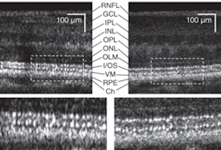
One image was acquired with an SLD providing approximately 6.5 µm axial resolution and the second was acquired with a SLD having approximately 3.5 µm axial resolution in tissue. The ultrabroadband light source clearly reduced speckle size in the axial dimension. In addition, we observed a change in the thickness at the photoreceptor layer junctions that act as reflecting surfaces; namely the photoreceptors’ inner and outer segment junctions and Verhoeff’s membrane (the end tips of cone photoreceptors outer segments). The difference in speckle size between the two OCT images seems to have an even bigger effect on visibility of retinal features.
Frame averaging
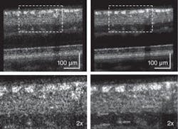
Next, we applied multiple-frame averaging to enhance image sensitivity (see Fig. 3).6 In this case, our AO subsystem was focused on inner retinal layers (the top three layers show increased intensity: the retinal nerve-fiber layer, the inner plexiform layer, and ganglion-cell layer). Frame averaging resulted in a clear speckle reduction and improvement in contrast observed between nerve-fiber bundles and some capillaries in the two images, making the AO-UHR-OCT images easier to interpret. Note that even for this large eccentricity, we observed that TCA had no clear effect on image lateral resolution or intensity. Moreover, microscopic scattering structures, probably single cell bodies, unrelated to speckle noise that lie within retinal layers are more readily observed.
The improved AO-UHR-OCT instrument was used for in vivo imaging of the retina in several subjects, allowing isotropic, ultrahigh volumetric resolution of 3.5 µm3. We used a custom achromatizing element to correct for the eye’s natural lateral chromatic aberration across the near-infrared wavelengths at which the ultrabroadband light source operated. We did not observe degradation of image quality attributed to transverse chromatic aberration, which suggests that TCA is small, as theory predicts. Cascading two wavefront correctors enabled diffraction-limited lateral resolution, while a large-stroke bimorph deformable mirror corrected high-magnitude, low-order aberrations. A high-fidelity microelectromechanical systems (MEMS) deformable mirror corrected low-magnitude, high-order aberrations. Overall, the combination of these features improved micron-scale three-dimensional resolution, and reduced speckle size significantly to improve visibility of microscopic structures in the retina, moving such instruments toward clinical applications.
ACKNOWLEDGMENTS
We gratefully acknowledge the contributions of Stacey S. Choi and Susan Garcia from UC Davis (Sacramento, CA) as well as Yan Zhang from Indiana University (Bloomington, IN). Thanks to Julia W. Evans and Diana Chen from Lawrence Livermore National Laboratory (Livermore, CA) for providing AO support and to Joseph A. Izatt from Duke University and Bioptigen (both Durham, NC) for providing OCT data-acquisition software. This research was supported by the National Eye Institute (grant EY 014743).
REFERENCES
- W. Drexler and J.G. Fujimoto, J. Biomed. Opt. 12, 041201 (2007).
- M. Pircher and R.J. Zawadzki, Expert Rev. of Ophthalmology 2, 1019 (2007).
- R.J. Zawadzki et al., J. Opt. Soc. Am. A 24, 1373 (2007).
- R.J. Zawadzki et al., Opt. Express 13, 8532 (2005).
- Y. Zhang et al., Opt. Express 14, 4380 (2006)..
- R.J. Zawadzki et al., Opt. Express 16, 8126 (2008).
- E.J. Fernández et al., Opt. Express 16, 11083 (2008).
Robert J. Zawadzki is an assistant researcher and John S. Werner is professor of vision science at the Advanced Retinal Imaging Laboratory (VSRI), University of California Davis, 4860 Y Str. Suite 2400, Sacramento, CA 95817; Barry Cense is a research associate and Donald T. Miller is associate professor of the School of Optometry, Indiana University, 800 E. Atwater Ave., Bloomington, IN 47405; and Steven M. Jones is research engineer and Scot S. Olivier is associate division leader of applied physics at Lawrence Livermore National Laboratory, 7000 East Ave., L-210, Livermore, CA; e-mail: [email protected]; vsri.ucdavis.edu.