PROJECTION DISPLAYS: Lasers and MEMS take video projection beyond HDTV
FORREST L. WILLIAMS and JAN N. BJERNFALK
Using lasers as light sources in conjunction with a unique silicon image-modulator chip, Evans & Sutherland (E&S) has developed laser-based digital projection displays for large-format applications such as planetariums and simulators. The Evans & Sutherland Laser Projector (ESLP) produces more than 33 million pixels, or 16 times the resolution of 1080-progressive-scan high-definition television (HDTV).
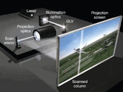
The core of the ESLP technology is the Grating Light Valve or GLV from Silicon Light Machines (San Jose, CA), which was invented by David Bloom while at Stanford University (Stanford, CA).1 The GLV is a one-dimensional (1-D) modulator, while most other modulators are two-dimensional (2-D) devices (see www.laserfocusworld.com/articles/328527). Other modulators consist of rows and columns of pixels, whereas a GLV modulator consists of only a single column of 4096 pixels. To form a 2-D image with a GLV, an image of the 1-D GLV column is scanned across the viewing surface within one frame. As long as the frame time is shorter than the persistence of vision, a 2-D image is created (see Fig. 1).
Resolution and the GLV
In the context of ultrahigh resolution, forming a 2-D image by scanning a 1-D column offers some distinct advantages. For example, to project an 8192 × 4096 image, a 2-D modulator would need to have more than 33 million active pixels in its construction. The GLV can provide this same resolution with just 4096 pixels in a linear array. Therefore, from a device standpoint, the GLV offers a potentially simpler approach to achieving ultrahigh resolution compared to current 2-D modulators. However, this advantage comes at a cost in the form of the “etendue” of the GLV.
In optics, the term etendue is used to represent how “compact” the light is from a source or image. It is a law of optics that the etendue of a system can never be reduced, but only increased through phenomena like aberrations or scattering. This has important ramifications when choosing a light source to illuminate a GLV.
Etendue of a source or image is defined as the area of the source or image multiplied by the solid angle subtended by the light emanating from the source or image (see Fig. 2). When discussing projection systems, the etendue of the modulator is given by the area of the modulator times the numerical aperture required to resolve the modulator‘s pixels in image space. In the case of our hypothetical 33-million-pixel 2-D modulator, the etendue would be approximately 10 mm2 ∙ sr (assuming 7.5 μm pixels and a wavelength of 532 nm). Because a GLV is a 1-D device, its illumination area is quite small, and this small area causes the GLV to have a very low intrinsic value of etendue, about 0.004 mm2 ∙ sr.
Low etendue
Most projectors use incandescent lamps as their light sources. However, the etendue of a lamp is quite large, typically 12.5 mm2 ∙ sr. Because the etendue of an 8192 × 4096 2-D modulator would be comparable to that of a standard lamp, it is reasonable to hope that most of the light from the lamp can be used to illuminate such a 2-D modulator. However, the same lamp illuminating a GLV would only achieve an illumination efficiency (the ratio of the GLV etendue to the lamp‘s etendue) of 0.03%. In other words, the lamp would have to emit more than 3 kW of optical power in order to get 1 W of light onto the GLV within the required envelope. Obviously, the GLV needs a much more efficient light source than that offered by lamps: the laser.
The etendue of an ideal laser is given by the square of its wavelength (λ2). A green laser operating at a wavelength of 532 nm will have an etendue of approximately 3 × 10—7 mm2 ∙ sr. Recalling that the etendue of a GLV is 0.004 mm2 ∙ sr, the ratio of etendues (approximately 13,000) would now be much greater than 1. This just means that it is possible to get all of the light from a laser onto a GLV within the required illumination envelope.
When E&S began to develop the ESLP in 1999, we discovered that there were no efficient high-power, continuous-wave (CW) visible lasers to be found. So we embarked on developing our own visible-laser technology. We soon realized that fiber lasers and amplifiers are ideal sources for nonlinear-conversion purposes. Consequently, we developed a technology for converting infrared fiber-laser light into visible output.2
Our fiber-laser sources use a master-oscillator power-amplifier (MOPA) architecture in which the output from a distributed-feedback (DFB) Bragg-grating fiber laser is amplified by a diode-pumped double-clad fiber amplifier. Fiber-based MOPA lasers typically operate with very high (usually 30%) “wall-plug” efficiency, generate up to 20 W (or more) of CW single-frequency, single-mode laser light, are compact, and are tunable. All of these traits lend themselves to nonlinear conversion.
Laser frequencies can be converted through a process in which two “fundamental” laser beams are combined in a nonlinear crystal to yield a single “harmonic” beam. The conservation of energy requires that the photon energy of the harmonic beam equal the sum of the photon energies of the two fundamental beams, thereby relating the wavelength of the harmonic λH to the wavelengths of the two fundamentals, λ1 and λ2, as 1/λH = 1/λ1 + 1/λ2. The most general situation is when λ1 ≠ λ2, in which case the process is called sum-frequency mixing (SFM). Second-harmonic generation (SHG) represents the special case when two photons from a single fundamental beam are combined (when λ1 = λ2) to create a harmonic beam whose wavelength is half that of the fundamental.
When using nonlinear conversion of fiber lasers to create three primary colors (red, green, and blue), the fiber lasers establish the fundamental wavelengths λ1 and λ2. There are only two such wavelengths currently available: 1064 and 1550 nm. These wavelengths, in turn, determine the processes used to generate the projector‘s RGB gamut. That is, the 532 nm green output is achieved through SHG of the 1064 nm source, and the 631 nm red wavelength comes from SFM with the 1064 and 1550 nm sources. Blue emission is arrived at through cascaded nonlinear conversion, in which SHG from 1550 nm is first used to generate 775 nm, and then successive SFM of this 775 nm light with 1064 nm creates 448 nm.
Bow-tie resonators
To achieve appreciable nonlinear-conversion efficiencies, very high fundamental intensities in the crystal are required (typically, 10 to 30 MW/cm2). This explains why pulsed lasers, with their high peak intensities, are often used to perform SHG and SFM. However, because the ESLP uses CW lasers (for reasons of eye safety), some other method must provide the kinds of intensities required. That method is power enhancement through the use of external resonators.
Optical cavities external to the fiber laser can resonantly build up fundamental powers to levels that are 35 to 50 times the power emitted by the fiber laser. By placing the nonlinear crystal in a focus within the cavity, maximum intensities within the crystal exceeding 15 MW/cm2 are achieved with 10 W of output from the fiber laser or “pump source.” With these kinds of resonant intensities, as much as 95% of the infrared-laser power incident on the cavity is converted to visible light.
For buildup to occur in a cavity, the beam path within the cavity must be an integer number of wavelengths. This establishes a fundamental frequency for the cavity that must be matched exactly by the pump source for resonance to occur. We use the so-called Pound-Drever-Hall phase-discriminant method to track the cavities‘ resonant frequencies, and tune either the fiber-laser frequency (by stretching the DFB laser) or the cavity length (by moving one of the cavity mirrors) to maintain the laser source and cavity in a resonant condition.3, 4 The bandwidth of the tuning circuit (electronics and actuators) is greater than 100 kHz, which allows it to respond to incidental mechanical and acoustic shocks that would otherwise cause the system to lose resonance.
If resonance is lost for some reason, 97% to 98% of the pump light will be reflected by the pump mirror rather than enter the cavity. Consequently, to avoid destroying the amplifier from this back reflection, the resonator is a ring cavity in a “bow-tie” configuration. Since the resonator is a ring cavity, pump light is incident on the pump mirror at non-normal incidence. Light reflected off of the pump mirror is directed at an angle that is not aligned with the pump laser, thereby avoiding damage to the fiber-laser system (see Fig. 3).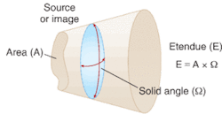
The laser systems currently manufactured by E&S produce at least 6 W of visible-laser power at 448, 532, and 631 nm, with short-term CW operation yielding up to 18 W visible-laser output per color. The lasers are single-frequency (full-width half-maximum bandwidth less than 200 kHz) spatially pure (M2 less than 1.05) TEM00 Gaussian beams that exhibit long-term power stabilities of better than 0.3% and wall-plug efficiencies of 5% to 10%.
Laser-induced damage (LID) on the facets of the crystals in the external resonators is the primary limitation to long-term operation at visible powers greater than 6 to 7 W, and efforts are under way to increase crystal LID thresholds to allow reliable operation at greater power levels. We are working to develop cavities with better hermeticity, and are investigating better polishing and optical-coating processes. In the meantime, these novel lasers are now in use in numerous 33-million-pixel ESLP projectors around the world in daily planetarium shows and are targeted at applications beyond projection display.
REFERENCES
- D.M. Bloom, F.S.A. Sandejas, and O. Solgaard, “Method and apparatus for modulating a light beam,” U.S. Patent 5,311,360 (May 10, 1994).
- F.L. Williams et al., “Apparatus and method for frequency conversion and mixing of laser light,” U.S. Patent 6,763,042 (July 13, 2004).
- R.V. Pound, Rev. Sci. Instrum. 17, 490 (1946).
- R.W.P. Drever et al., Appl. Phys. B 31, 97 (1983).
Forrest L. Williams is principal optical engineer and Jan N. Bjernfalk is director of sales and marketing at Evans & Sutherland (E&S), 770 Komas Dr., Salt Lake City, UT 84108; e-mail: [email protected]; www.es.com.