FOCAL-PLANE ARRAYS: Nanohole arrays enable multiple-point-source imaging

A new type of focal-plane array made of a nanoscale metal screen mimics the function of a lens, focuses light (and plasmons) into subwavelength hot spots, and achieves high-resolution imaging of complex sources.
NIKOLAY I. ZHELUDEV, FU MIN HUANG, AND F. JAVIER GARCÍA DE ABAJO
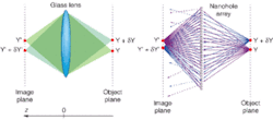
Typically we think of imaging devices in terms of either focusing light or focusing waves. In conventional optics, a glass lens images a point light source on one side of the lens to a focal point on the other via refraction. In wave optics, a lens focuses a wavefront via a gradual change of the phase delay, leading to an interference-driven convergence of the beam. In fact, for 170 years we have known of another type of imaging device. This first nanophotonic device, a regular array of nanoholes, was manufactured and studied by Henry Talbot in 1836.1 His study of how light travels through the array led to what is known as the Talbot effect of self-imaging: the field at the array is replicated at regular Talbot intervals, creating multiple light foci.
Recently a collaboration at the University of Southampton (Southampton, England) and the Instituto de Optica (Madrid, Spain) demonstrated that a more complex arrangement of nanoholes, neither regular nor random, known as the Penrose-like quasi-crystal (see en.wikipedia.org/wiki/Penrose_tiling), can create “hot spots” of electromagnetic radiation.2,3 Moreover, the hot spots created by the Penrose array behave similarly to a conventional glass lens: an object placed into the hot spot is imaged on the other side of the array much like a glass lens images a point from the object plane to the image plane (see Fig. 1). The main difference between a glass lens and a nanohole-array lens is that a glass lens has a single focus, while a nanohole array has multiple foci located all around the proximity of the array.
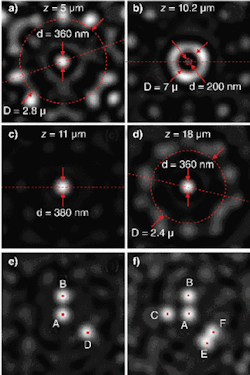
The good news is that the Penrose-like array at certain distances creates spatially isolated foci that can be conveniently used for imaging applications.4 We illuminated such a Penrose array with a 600 nm point source positioned 11.4 μm beneath the array. The multiple foci created by the Penrose array result from constructive interference of waves emanating from a large number of holes in the array. The characteristics of the foci vary from spot to spot (see Fig. 2). However at certain distances (for example, z = 11 μm,) well-isolated spots are found. If the point source is displaced along the array, the focus moves progressively in the opposite direction: the array performs a one-to-one imaging function mimicking that of a conventional lens.
Using the Penrose array, our group achieved faithful imaging of complex structures composed of multiple point sources with resolutions comparable to those of conventional lenses with high numerical apertures (NAs)—equivalent NAs up to 0.89 were demonstrated. As with focusing by a conventional lens, the focal spot size depends on the available wave-vectors of the interfering waves; in other words, on the solid angle of the interfering waves, with larger solid angles (higher NAs) giving better focusing. For the foci located a few wavelengths from the array, the number of constructively interfering waves coming from nearly a half-space solid angle (2 ∏ steradians) is high, thus enabling a tight focus.
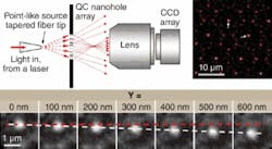
We further demonstrated nanoarray lensing in a simple experiment in which a tapered fiber of a scanning near-field optical microscope probe with a subwavelength aperture of 100 nm was used as a light source (see Fig. 3). Its image on the other side of the array was registered by a charge-coupled-device (CCD) camera, which confirmed that when the fiber tip moves, its image moves progressively in the opposite direction.
Further intriguing experimentation showed that nanohole arrays can generate subwavelength hot spots. The formation of subwavelength spots is fully explained by diffraction theory and is linked to a phenomenon of superoscillation.5 One therefore could argue that a resolution better than that of a conventional lens with NA = 1 could in principle be achieved with a nanohole array.6 Although the Penrose hole array can create subwavelength foci as small as 200 nm in diameter, the field of view is not sufficiently large for practical imaging applications. However, the superoscillation theory predicts that arbitrarily large fields of view with arbitrarily small foci are achievable with complex gratings. Here, the price to pay for high resolution in a large field of view will be a dramatic decrease in the power concentrated in the hot spot relative to the power going into the unfocused sidebands located outside the field of view.
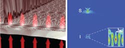
These concepts are not exclusive of light. They are applicable to other types of waves, including those bound on planar surfaces, and in particular, surface-plasmon polaritons (SPPs), which are a hybrid of electromagnetic fields and electrical currents bound to the surface of a metal.7 At near-infrared frequencies, surface plasmons propagate along gold and silver surfaces for hundreds of wavelengths, and are scattered by surface features like particles, dimples, and holes. When these scatterers are appropriately arranged, long-range interference produces the desired hot spots at large distances from the source. Two examples of this effect are self-imaging of a hole array in a plasmon analog of the Talbot effect,8 and a plasmon phase antenna operating in the near field and capable of refocusing the waves emanating from a point object to a distant point (see Fig. 4).9
We produced both these effects using silver nanoarrays. To achieve the plasmon Talbot effect, we transmitted 1.55 μm light through a periodic one-dimensional array of nanoholes with a period of 7.7 μm, which created a “Talbot carpet” of interfering plasmon waves. At self-imaging distance from the array (approximately 77 μm), the propagating plasmons revived, giving rise to plasmon focal spots. To create a plasmonic phase antenna, we sent light of the same wavelength through a conveniently designed nonperiodic array. Plasmons emanating from a point source S were scattered by an array of surface features—dimples placed in a nonperiodic array along the central line separating image and source—and refocused 31 μm away at an image spot I.9
These different approaches share in common the goal of producing extraordinary focusing of light in various forms (freely propagating light waves, surface-plasmon waves) by diffraction alone and suggest new platforms for imaging and optical interconnects.
REFERENCES
- H.F. Talbot, Philos. Mag. 9, 401 (1836).
- F.M. Huang et al., Appl. Phys. Lett. 90, 091119 (2007).
- F.M. Huang et al., J. Opt. A: Pure Appl. Opt. 9, S285 (2007).
- F.M. Huang et al., Nano Lett. 8 (8), 2469 (2008).
- M.V. Berry and S. Popescu, J. Phys. A: Math. Gen. 39, 6965 (2006).
- G. Toraldo Di Francia, Supplto. Nuovo Cim. 9, 426 (1952).
- H. Raether, Surface Plasmons on Smooth and Rough Surfaces and on Gratings, Springer-Verlag, Berlin (1988).
- M.R. Dennis et al., Opt. Express 15, 9692 (2007).
- A.G. Curto and F.J. García de Abajo, Nano Lett. 8(8) 2479 (2008).
NIKOLAY I. ZHELUDEV is professor and deputy director of physics, and FU MIN HUANG is research fellow at the Optoelectronics Research Centre, University of Southampton, SO17 1BJ, England; F. JAVIER GARCÍA DE ABAJO is professor at Instituto de Optica — CSIC, Serrano 121, 28006 Madrid, Spain; e-mail: [email protected]; www.orc.soton.ac.uk.
Tell us what you think about this article. Send an e-mail to [email protected].