PLASTIC OPTICS: Polymer optics gain increased precision
SHARI POWELL AND DANIEL FISHER
Just as plastic ophthalmic lenses gained wide acceptance first in European, then in Asian and U.S. markets, optical-system designers are increasingly choosing polymer materials for a multitude of non-ophthalmic applications in global markets ranging from cell-phone cameras to security and monitoring instrumentation. While the overall driving force for this increasing interest in plastics is often cost reduction, it is not always true that the individual plastic component is cheap.
Often, performance is the key factor forcing consideration of plastic materials. For instance, polymer optics are much lighter in weight than their equivalent glass components; less weight is frequently essential to the success of the envisioned system. Even more substantive performance benefits than lower weight are attainable when a system designer incorporates increased complexity into the optical components. These observations are not new, yet the increasing market pull for polymer optical components is reinforcing these considerations in the design of many new optical systems.1
The complexity that is attainable in optical and mechanical system parameters provides significant cost benefits to the overall system because plastic components can easily include aspheric optical-surface profiles, as well as flanges and other physical or alignment features that facilitate mounting and assembly. Yet the ability to design components with increased complexity is not only an asset but often the key to understanding failures when plastic optical components are first produced.
Production methods
The optimal production method for any given optical design in polymer is dictated by how well it achieves the design details as well as the volume of components required. The primary methods used to produce thermoplastic optical components include diamond turning, compression molding, and injection molding. Because a product’s production volume varies throughout its lifecycle, it is typical that more than one of these methods is used for the same plastic part at different times.
Diamond-turned optics can be machined to final surface finish in some polymer materials. This method is preferred for limited volumes of product (prototype quantities) or for components with specific, demanding technical requirements. Costs for diamond turning are comparable to high-precision machining operations.
Compression molding uses a relatively simple mold and can produce moderate volumes of the desired optical component. Its advantage is that mold fabrication costs are less than that of injection molding and yet much can be learned from the compression-molded parts, as they more closely represent the optics attainable from the higher-volume injection-molding process. In addition, the complexity of some components dictates that compression molding is the more economical means of achieving the required volumes.
Injection molding requires more-demanding mold designs, often including multiple cavities to reduce the per-part prices. However, there can be significantly higher engineering and mold fabrication costs incurred at the start of this process and the difficulty of the optical component may not allow large numbers of cavities to be successfully operated. This production method often incorporates process variations-such as adding compression into the cavity volume or varying the temperature profile throughout the mold cycle-to attain the precision required for successful fabrication of complicated plastic optics in single or multiple-cavity molds.
In each of these production methods, adjustments must be made to achieve parts that meet the end user’s needs. For instance, shrinkage during molding must be considered to achieve proper results, but for very precise lenses, the initial estimate to account for shrinkage in the mold design is only the beginning of the process. State-of-the-art lenses require consideration of complex material variations due to part geometry, mold design, and the molding-process conditions. While molding experience and process models can provide a good initial test run, some iteration is commonly needed to properly adjust the mold inserts and maintain processing parameters to achieve compliance when making precise imaging lenses. An understanding of these engineering requirements is essential for the supplier’s success, and an awareness that these efforts are needed to achieve precision in plastic greatly assists the customer’s program planning.
Polymer materials
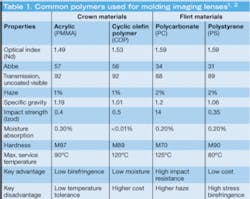
Several polymer materials are used in injection molding of visible imaging optics (see Table 1). The most common “crown” types are acrylic (PMMA) and cyclic olefin polymer (COP), while the most common “flint” types are polycarbonate (PC) and polystyrene (PS). Other intermediate index and specialty polymers are also available.
Large lenses are most commonly fabricated from PMMA and PC and small to medium lenses from COP and PS. While PMMA remains the most common material used in diamond turning of lenses and also for molding precision lenses, COP-the newest material in this quartet-is increasingly used because of its lower weight and very low moisture retention (and low affect on index due to moisture variations), despite its slightly higher cost. However, COP can have greater stress-induced problems than PMMA, which must be overcome by proper handling and optomechanical mounting.
Injection-molding example
The number of suppliers of plastic optics has increased substantially in the past several years and many original suppliers are adding capabilities that increase the complexity of the components they are able to produce. While each supplier makes various proprietary adjustments to reach compliance with the design, it is useful to show some typical steps required for the successful fabrication of a plastic imaging lens.
In one example, a double-convex lens designed as a polymer optic includes some of the advanced features readily available on a plastic lens, including aspheric surfaces and optomechanical mounting features (see Fig. 1). This type of imaging lens for visible wavelengths can have optical surface-roughness tolerance of 10 to 20 nm and an aspheric surface-accuracy tolerance of 2 µm (about 3 waves). The lens, approximately 1 in. in diameter and circularly symmetrical, is suitable for high-volume fabrication by injection molding once a mold is made and both the mold and the processing parameters are adjusted.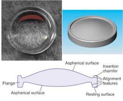
Molding adjustments
Measurements of the surface profile for several iterations of a molded lens can be taken (see Fig. 2). These measurements are each a composite of a statistical sampling of several parts made in a given mold run. The specified profile for the desired top surface (shown in Fig. 1) is set as the reference and the measured difference from this goal is plotted against the clear aperture of the part. A flat line would thus indicate 100% match with the target surface profile.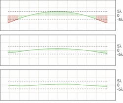
At first, the part is not within a ±5-wave window of variation from the ideal profile. The data reflecting this variation is analyzed, appropriate changes to the mold and process are made, and a new set of parts are then fabricated.
In the first corrected-lens mold run, the part’s profile is brought to within a ±5-wave range of compliance with the specification. In this instance, a decision was made to further tighten up the tolerance and rework the mold and process once again to get to within ±2 waves of the ideal surface profile.
In the final corrected-lens mold run, the surface of the molded part is well within the ±5-wave tolerance band. The surface is now reproducible using standard operating parameters and statistical process-control techniques throughout the injection-molding operation. Similar adjustments are made for each critical parameter and interactions between surfaces are carefully considered.
Tolerancing
While mold and process corrections can greatly aid the ability to hold tighter optical tolerances on some features, not all the critical concerns are purely optical. Some mechanical alignment features critical to the assembly of this type of lens must be precisely molded along with the optical surfaces.
For example, optomechanical features such as the outer flange shown in Fig. 1 can be incorporated along with an injection-molded housing for easier, lower-cost assembly. The entire lens package will end up much lower in weight than a metal housing with metal spacers, tubes, and retaining rings. Moreover, an integrated optomechanical analysis incorporating thermal-property simulations, such as thermal expansion of the materials, change in refractive index with temperature (dn/dT), and so on, can achieve much better results for the combined tolerance set of the lens-housing package.
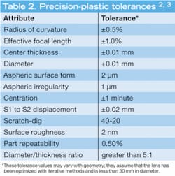
A good place to start regarding tolerancing of important imaging lenses made from plastic materials is to use state-of-the art tolerances (see Table 2). These tight tolerances will cost considerably more than commercial-grade tolerances. A number of iterations of the mold tool and process may be needed to get to these levels of accuracy. In Optical System Design, author Robert E. Fisher states that “tolerances do not lie” but also that tight tolerances are very costly.4 For glass optics, tight tolerances could cost three to four times as much as standard commercial-grade tolerances; this is also true for molded polymer optics.
To successfully incorporate greater precision into the manufacture of plastic optical components, one must recognize the all-important connections linking optical design, mold-making, and injection molding. If these activities are performed in different locations or are under disparate control, then success may be very difficult to attain at any cost, since good communication between each of these activities is essential.
The key to success when fabricating complicated polymer optics is an understanding of which optical surfaces or mechanical features require the highest accuracy, and balancing those with what can actually be achieved in production. When all sides work together to overcome the limitations of plastic materials, the full advantages of plastics can be utilized to add greater functionality to a polymer optic, as well as lower the production costs for the entire optical system.
REFERENCES
1. W.J. Smith, Modern Optical Engineering, McGraw-Hill (2000).
2. S. Baumer, Handbook of Plastic Optics, Wiley-VCH (2005).
3. Polymer Optics internal data.
4. R.E. Fischer, Optical System Design, McGraw-Hill (2000).
SHARI POWELL is vice president and DANIEL FISHER is president of Polymer Optics, 3100 Dutton Ave. 118, Santa Rosa CA 95407; e-mail: [email protected]; www.polyoptics.com.