BIOMEDICAL OPTICS: Surface reflections reveal hidden eye misalignments
JUAN TABERNERO AND PABLO ARTAL
Purkinje images have been a traditional source of information in studying the optics of the eye. A light source illuminating the eye generates specular reflections at the different ocular interfaces (air-cornea, cornea-aqueous, aqueous-crystalline lens, and lens-vitreous) that are commonly named Purkinje images (PI, PII, PIII, and PIV, respectively), after Jan Purkinje, a Czech physiologist that made use of them in the 19th century.
In the early times of physiological optics, these Purkinje images were the primary source used to obtain information about ocular structures such as an understanding of the accommodation mechanism (the autofocus system for near vision), the calculation of the radii of curvature of the ocular components, or the estimation of the alignment axes of the human eye.1 However, because early experiments used the reflection of candle light to generate Purkinje images, quantitative results were limited.
Purkinje applications
The advent of new optical technologies including CCD cameras and light sources such as lasers and light-emitting diodes (LEDs) opened many practical possibilities for the use of Purkinje images to further study ocular optics. In step with these developments, advanced ocular surgeries have created a variety of applications for ocular optics. After cataract surgery, the decentration and tilt of implanted intraocular lenses are important aspects of stable optical performance.2, 3, 4 Other clinical applications include the use of Purkinje images for the screening of strabismus and other fluctuations of the ocular axes.5 Yet another popular application is the development of dual eye-trackers that make use of the corneal reflection (PI) and the lens posterior reflection (PIV).
We have recently developed a Purkinje-based instrument that can be used in some of these potential clinical applications and that also serves as a tool for basic studies in the human eye.6 The instrument is especially relevant to confirming recent discoveries of the relationship between aberrations of the ocular components (cornea and crystalline lens) and the natural alignment properties of the eye.7
Instrument specifics
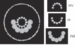
Our instrument uses a semicircular array of infrared LEDs to generate PI (air-cornea interface), PIII (aqueous-crystalline lens interface), and PIV (lens-vitreous interface) Purkinje images. In an ideal case when the optical components of the eye are all well-aligned, a computer simulation of the reflection pattern from an eye model that is perfectly aligned with the semicircular source would present three well-aligned semicircular rings (see Fig. 1). This nonsymmetrical source is used because of the typical optical properties of the eye: the magnification for PIV has a sign opposite to that of the magnification of PI and PIII. Also, it is interesting to note that PIII has a typical size of around twice PI and PIV. Besides the semicircular LED source, it is also possible to use other types of sources.8
When a human eye fixates to a point, Purkinje images are typically seen misaligned. There are three possible causes for this: a global eye rotation, lens decentration, and lens tilt. These three causes are each physiologically plausible and they can act in combination. Alignment of PI, PIII, and PIV is not possible when any of these three conditions are present.
However, it is always possible to align PIII and PIV (lens reflections) by moving the source in front of the eye or, similarly, changing the fixation of the eye with respect to a fixed source. The overlapping position of PIII and PIV provides the location of the optical axis of the crystalline lens. The angular distance from the centrally aligned fixation point to that fixation when overlapping occurs will approximate lens tilt (with respect to the line of sight). And the distance from the geometrical pupil center to the overlapping point of PIII and PIV gives an estimation of lens decentration.
This procedure is implemented in the measurement instrument by making the subject fixate sequentially at nine different angular targets (see Fig. 2). The more peripheral points in the fixation LEDs subtend an angle of 5° with respect to the central stimulus. An image of the anterior eye containing Purkinje images is recorded at each fixation position, and the distance from each reflection to the center of the pupil is obtained. These distances are plotted as a function of the angular fixation. From these plots, by linear interpolation (or extrapolation, depending on the subject), the fixation angle where the third and fourth Purkinje images overlap can be determined.
Clinical experiments
An example of the procedure for one particular real subject produces complex Purkinje images (see Fig. 3). Nine images-one for each fixation position-display the three reflections PI, PIII, and PIV. The position of each reflection can be located with respect to the pupil center and the overlapping position can be extrapolated. This multiple fixation test makes the instrument especially robust and the simple, compact design makes it appropriate not only for the research lab but also for a clinical environment.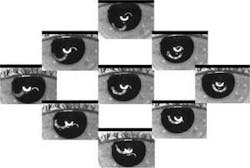
One of the most promising applications of the instrument is to measure the misalignment in eyes implanted with intraocular lenses (IOLs). In particular, those eyes implanted with aspheric IOLs have more relevant interest. The aspheric profile of these lenses was designed to compensate for the average spherical aberration of the cornea in a similar way to the situation occurring in young eyes.9, 10 However, this profile renders the eye more sensitive to IOL misalignments and-in the worst possible case-it is possible that the visual benefit achieved with the correction of spherical aberration would be totally reduced by the increase of other off-axis aberrations such as coma. In this context, measurement of the typical misalignments of the IOL has a critical relevance. The instrument presented here has been successfully applied to measure eyes implanted with aspheric lenses. The results have been used to establish the limits of tolerance to decentration and tilt for these IOLs using a customized ray-tracing procedure.11
The application of the instrument for more basic science is also promising. Several studies have shown the compensation effect between corneal and crystalline lens coma aberration. The origin of this systematic effect seems to be related to the alignment properties of the eye, especially due to a systematic horizontal tilt of the ocular optics with respect to the line of sight. Our instrument provides direct and definitive evidence of this effect and can obtain a better description of the optical properties of the eye. Some studies using our instrument have already shown that the main contribution to the compensation effect of the eye is the horizontal tilt component of the eye’s optical components (cornea and crystalline).12
ACKNOWLEDGMENTS
This study was supported in part by the Ministerio de Educación y Ciencia, Spain (grant FIS2004-2153 to PA).
REFERENCES
1. H. Hemholtz, “Treatise on Physiological Optics,” Dover, NY (1925).
2. P. Phillips et al., J. Cataract Refract. Surg. 14, 129 (1988).
3. J.D. Auran, C.J. Koester, and A. Donn, Arch. Ophtalmol. 108, 75 (1990).
4. D.L. Guyton, H. Uozato, and H.J. Wisnicki, Ophtalmol. 97, 1259 (1990).
5. J.C. Barry et al., Invest. Ophthalmol. Vis. Sci. 35, 4219 (1994).
6. J. Tabernero et al., Optics Express14, 10945 (2006).
7. P. Artal, A. Benito, and J. Tabernero, J. Vis.6, 1 (2006).
8. P. Rosales and S. Marcos, J. Opt. Soc. Am. A 23, 509 (2006).
9. A. Guirao et al., Arch. Ophthalmol. 120, 1143 (2002).
10. P. Artal et al., J. Vis. 1, 1 (2001).
11. J. Tabernero et al., Invest. Ophthalmol. Vis. Sci. 47, 4651-4658 (2006).
12. P. Artal, J. Tabernero, and A. Benito, Invest. Ophthalmol. Vis. Sci. 47, E-Abstract 1501 (2006).
Juan Tabernero is a research student and Pablo Artal is a professor at the Laboratorio de Óptica, Universidad de Murcia, Campus de Espinardo (CiOyN), 30071 Murcia, Spain; e-mail: [email protected]; www.um.es.