FIBERS FOR FIBER LASERS: Higher-order mode propagation may enable power scaling
Scaling the power levels of fiber lasers has received much attention recently as a source of potential competition for bulk solid-state lasers. In addition to being lighter and more compact, fiber lasers offer the prospect of achieving higher powers than bulk lasers because distributed gain available from a long length of fiber enables efficient thermal management.
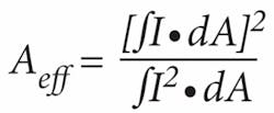
The long fiber lengths that make fiber lasers attractive, however, also pose the primary bottleneck in scaling power levels. Propagating intense light through meter-long fibers leads to nonlinear distortions such as stimulated Raman scattering, stimulated Brillouin scattering, self-phase modulation, and related parametric processes. Mitigating these effects requires fibers in which the optical mode occupies a large modal area, and hence is less intense. Therefore, much of the recent development effort in the field of high-power fiber lasers has focused on large-mode-area (LMA) fibers. The effective mode area (Aeff) of a fiber is defined as:
where I is the mode intensity, and dA signifies integration over the cross-sectional area of the fiber.
The straightforward and conventional means to achieve large Aeff is to scale the fiber dimensions. The tradeoff is that this makes the fiber multimode, leading to poor output beam quality.1 Nevertheless, laboratory demonstrations using this approach have achieved Aeff as large as 2000 µm2, though they required great precision in input-coupling and fiber-handling.2
An alternative approach uses microstructured optical fibers (MOF) that offer additional design flexibility by selectively leaking higher-order modes.3 Thus, Aeff up to roughly 1400 µm2 has been demonstrated in fibers that can be spliced and packaged. A variant of MOFs, a rigid glass rod, has gained much recent attention because a straight light-guide can clearly afford scaling of Aeff.4 Modal areas up to 4500 µm2 have been achieved, but such structures are limited to short lengths, need free-space coupling, and are in fact conceptually closer to solid-state rod lasers, though they offer better thermal management.
A fourth approach was recently demonstrated—instead of using the conventional fundamental mode, a single higher-order mode (HOM) is efficiently excited in an intentionally few-moded fiber. This is a somewhat counterintuitive approach because conventional wisdom dictates that multimode fibers are susceptible to mode mixing and noise, and that HOMs leak out and are therefore more lossy than the fundamental mode. However, we will show that in an appropriately designed fiber the modal stability of HOMs can actually be greater than that of the fundamental mode, provided that the desired HOM is excited with very high modal purity. Thus, HOM fibers have enabled robust light propagation with record levels of Aeff (exceeding 3000 µm2).
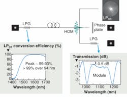
Because HOMs do not resemble Gaussian transverse shapes (as do the spatial distributions of conventional fibers and most bulk-optic lasers), exploiting the enhanced stability of HOMs requires mode-transformation techniques, which involves a three-step process (see Fig. 1). The signal is introduced into the fundamental mode of the fiber, which can be achieved with splices, collimation, and/or focusing. Thereafter, the signal is transformed into the desired HOM in an ultra-large-mode-area fiber with an in-fiber long-period grating (LPG; with grating periods typically ranging from 50 to 1000 µm). Because the transformation involves converting a single lower-order mode into a single higher-order mode, it is achieved by resonant coupling—a highly efficient process with experimentally measured conversion efficiencies better than 99%.5
After propagation over the desired length, the single high-order mode at the output can be utilized in one of three ways: because it is a spatially coherent beam, it can be relayed through lenses and other optical elements just as with any other beam; holographic phase plates can efficiently convert the HOM back to a Gaussian-like shape; or an LPG with similar characteristics as the input LPG would perform the mode-conversion in reverse—from the HOM to the fundamental mode. The spectrum of a module that comprises an output LPG and another one at the input is shown in the inset of Fig. 1 on the right—note that the broadband, efficient nature of the long-period grating, combined with the robust, spliceable nature of the higher-order-mode fiber yields a device with a 1 dB bandwidth exceeding 100 nm.
Mode stability and distortion
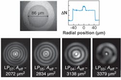
While a pure modal output is achieved for the modal orders ranging from LP04 to LP07 in a few-moded fiber used to obtain ultra-large-mode-area HOM propagation, the LP03 mode shows significant distortion and mode coupling (see Fig. 2). This is an interesting and counterintuitive result, which suggests that mode stability actually increases with mode order. Mode stability, or the lack of mode coupling, typically increases as the difference in modal indices between the desired mode and the nearest antisymmetric mode increases. Numerical simulations on this fiber reveal that the difference in modal indices between the desired LP0,m mode (m represents an integer for various radial orders) and the closest antisymmetric mode (LP1,m) increases with modal order (m). Thus, it confirms our experimental observation that the mode stability as well as resistance to mode coupling increases with increasing mode order.6
This concept has far-reaching consequences for designing fibers with very large mode areas. Typically modal index spacing decreases as fiber dimensions increase—indeed this is the fundamental reason that robust fundamental mode propagation in conventional LMA fibers is limited to Aeff of approximately 1400 µm2, as noted earlier. But while this rule exists for every mode in the fiber, our observation and simulations indicate that the modal-index separation can be enhanced by operating in increasingly higher-order HOMs. This means that for a sufficiently strongly guided fiber waveguide, one can always find a mode order with sufficiently large modal-index separation (from the nearest antisymmetric neighbor). Hence, the HOM platform is significantly more scalable in achievable Aeff than conventional, fundamental-mode fibers. Utilizing this scalability, HOMs have achieved the largest Aeff to date (3200 µm2) among flexible fibers.
Higher-order modes offer another advantage over fundamental-mode LMA fibers. A bent fiber has a “slanted” equivalent refractive-index profile that serves to push the mode away from the direction of the bend. For the conventional LP01 mode, this results in a sharp decrease in Aeff, and the effect becomes increasingly pronounced for larger Aeff LP01 modes. When held straight and bent to radius of 6 cm—the dramatic change in modal shape results in an Aeff reduction of approximately 50% in a conventional LMA fiber with an 800 µm2Aeff for the LP01 mode (see Fig. 3). In contrast, an LP07 mode with even larger Aeff (about 2000 µm2) undergoes a negligible change in mode shape or Aeff when bent down to a radius of curvature of 4.8 cm.7 Experimental observations of bend loss and mode extinction in bent HOM fibers, while not directly measuring changes in modal shape, confirm the HOM’s resistance to bends—the excess loss or mode coupling (mode coupling is defined as the fraction of light in undesired modes) remain negligibly low until a bend radius of approximately 4 cm.
Optical properties
Higher-order modes in specially designed few-mode fibers have two attractive attributes in addition to modal stability. The choice of modal order provides a range of achievable effective area. Because the inner-cladding layer that primarily guides the higher-order modes is a high-index-contrast waveguide, the mode remains tightly confined over a range of wavelengths. The result is that the design is relatively insensitive to wavelength, and the effective area remains large (and similar) over a large spectral range (over a wavelength range of 500 nm, the Aeff of the LP07 mode of Fig. 2 changes by only 6%).
The other interesting feature of this platform is the ability to tailor the dispersion of the mode. Dispersion tailoring with the conventional LP01 mode is restricted to designs that have relatively small effective areas (typically ranging from 10 to 60 µm2). For LMA designs, light in the LP01 mode resides exclusively in a large single-index guiding layer, and its dispersion is essentially that of the material in which it resides. In contrast, it is well known that higher-order modes provide significantly greater design flexibility in dispersion tailoring.8, 9 For the large-mode-area HOMs described in this article, the waveguide dispersion becomes increasingly positive as the mode order increases, such that it can be feasible to obtain anomalous dispersion even at 1060 nm, a property of potentially great interest in constructing 1060 nm femtosecond lasers.10
In addition to the other advantages detailed above, doping large-mode-area HOMs with rare-earth ions yields amplifiers, just as in the case of conventional LMA fibers.
ACKNOWLEDGMENTS
The authors thank M.F. Yan, S. Ghalmi, J.W. Nicholson, J.M. Fini, M. Mermelstein, K. Brar, F. Dimarcello, E. Monberg, C. Headley and D.J. Digiovanni for insightful discussions and experimental support. This work was partially supported by the U.S. Department of Commerce, National Institute of Standards and Technology, Advanced Technology Program, Cooperative Agreement Number 70NANB4H3035.
REFERENCES
1. M.E. Ferman, Optics Lett. 23, 52 (1998).
2. K.-H. Liao et al., CLEO 2006, PD Paper CPDB4.
3. W.S. Wong et al., CLEO 2005, paper CPDB10.
4. J. Limpert et al, Optics Exp. 14, 2715 (2006).
5. S. Ramachandran, J. Lightwave Tech. 23, 3426 (2005).
6. S. Ramachandran et al., Optics Lett. 31, 1797 (2006).
7. J.M. Fini, S. Ramachandran, Opt. Lett. 32, 748 (2007).
8. S. Ramachandran et al, OFC 2006, Post-deadline paper PDP3.
9. S. Ramachandran et al, Optics Lett. 30, 3225 (2005).
10. J.W. Nicholson, S Ramachandran, et al., Optics Lett. 31, 3191 (2006).
11. S. Ramachandran et al., Post-deadline Paper, LBN-7, Photonics West 2007.
About the Author
Siddharth Ramachandran
Siddharth Ramachandran is a distinguished professor of engineering at Boston University. He started his career in industrial research at Bell Labs, and his work with light-wave devices has helped advance optical networks, laser-based defense systems, brain imaging, and quantum computing.


