IMAGING OPTICS: Artificial compound eye applies hyperacuity
Researchers at the Fraunhofer Institute for Applied Optics and Precision Engineering (IOF) and at Friedrich Schiller University Jena (both in Jena, Germany), are applying hyperacuity—the natural phenomenon of seeing motion or images with an accuracy exceeding that of the vision system’s capabilities—to access highly accurate information beyond the resolution limit of an artificial compound eye.1
In nature, a number of insects can detect motion in a limited field of view (FOV) within a fraction of their photoreceptor diameter; in other words, they can achieve hyperacuity (or subpixel accuracy) through image segmentation, information pooling, and parallel signal processing. Artificial compound lenses based on the eyes of insects can be used in applications where small size and cost-effective fabrication are crucial; however, these compound-eye imaging systems are reaching their resolution limits as the imaging systems become miniaturized. But by applying the concept of hyperacuity to these compound-eye systems, the accuracy for extracting position information or motion can be improved.
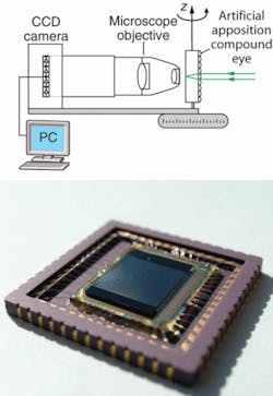
To demonstrate the technique, the researchers fabricated an artificial compound eye as a microlens array on a planar glass substrate. To complete the imaging system, a sensor array with a pixel pitch different from that of the array was placed at the focal plane of the microlens array (reimaged via a relay lens) to record the image. To improve resolution, a pinhole array was placed at the actual (nonrelayed) focal plane of the microlens array (see figure).
In this multiaperture imaging device, the object space is sampled by the angular-sensitivity functions of the different optical channels, which exhibit a finite angular width. The width is characterized by the acceptance angle, which also approximates the smallest resolvable angle between two image details. For example, 84 × 64 channels are sampling an overall FOV of 25° × 25° with an acceptance angle of 0.65°. The overlap between the FOVs of adjacent optical channels enables the extraction of subpixel information when the profile of the ASF is known.
Signal independent of irradiance
An object—represented by a contrast change—at some angular distance from the optical axis of one channel causes different intensities within the focal planes of adjacent channels. Each of the intensities is proportional to the value of the individual angular-sensitivity function at the angle under which the object is observed. The ratio between them gives a signal that is independent of the absolute irradiance of the source and other unknown parameters such as the transmission of the optical system. This signal is used to calculate an analytical and unique relationship between the measured intensities of adjacent channels and the position of the object within the FOV of one channel.
The overlapping information from each of the pixels is used to improve the object localization of the low-resolution compound-eye imaging system. For example, position information was extracted from an image containing 50 × 50 pixels with an accuracy of 500 × 500 effective pixels. Accuracies up to a factor of 50 better than the smallest resolvable feature size have been achieved; however, the signal-to-noise ratio of the imaging system limits the highest achievable accuracy.
“When I first read about the resolution limit of a fly’s eye, I wondered why it is so hard to catch one,” said researcher Andreas Brückner. “Then, I learned about hyperacuity and the information processing in the synaptic layers of an insect eye. These little creatures teach us a different approach for navigation sensors without the need for high resolution or massive image processing. The combination of artificial compound eyes with programmable image sensors or smart pixels is a way to exact navigation with less data needed. This is crucial in autonomous machine and robot vision, for example.”
REFERENCE
1. A. Brückner et al., Optics Express 14(25) 12076 (Dec. 11, 2006).
About the Author

Gail Overton
Senior Editor (2004-2020)
Gail has more than 30 years of engineering, marketing, product management, and editorial experience in the photonics and optical communications industry. Before joining the staff at Laser Focus World in 2004, she held many product management and product marketing roles in the fiber-optics industry, most notably at Hughes (El Segundo, CA), GTE Labs (Waltham, MA), Corning (Corning, NY), Photon Kinetics (Beaverton, OR), and Newport Corporation (Irvine, CA). During her marketing career, Gail published articles in WDM Solutions and Sensors magazine and traveled internationally to conduct product and sales training. Gail received her BS degree in physics, with an emphasis in optics, from San Diego State University in San Diego, CA in May 1986.