ELECTRO-OPTICS: Hybrid polymer/glass fiber senses electric fields

While small electro-optic (EO) probes that sense the electric fields near power lines and other power-station components have been under development for years (see www.laserfocusworld.com/articles/26658), further decreasing their size would open up more practical applications. One common geometry is a planar EO dielectric-waveguide structure coupled to an optical fiber. Now, researchers at Brigham Young University (BYU; Provo, Utah) and Ipitek (Carlsbad, CA) have eliminated the larger structure and integrated the EO capability into the fiber itself, making the new device potentially as easy to situate and use as any other fiber sensor.1
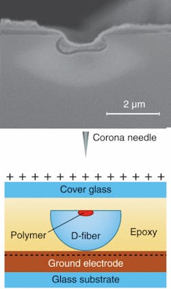
The researchers start with a polarization-maintaining elliptical-core fiber designed for a 1550 nm wavelength and with a D-shaped cross section, etch the fiber to partially expose its core, then coat the core and cladding with an EO polymer (a fiber designed for use at 860 nm could also be used if desired). The fiber core is germania-doped and is surrounded by a fluorine-doped cladding and an undoped supercladding; because the core etches faster, a groove is created by the partially etched-out core (see figure). The polymer is a mixture of poly(methylmethacrylate) and Disperse Red 1. After coating and encapsulating in epoxy, the polymer is “poled” (endowing it with EO properties) by bringing an electrically charged corona needle near to it in a controlled process. (While the researchers could have skipped the polymer entirely and relied on the nonlinear properties of the germania-doped glass core, the polymer has a much larger EO effect.)
Aligning the polymer molecules
In the poling process, the polymer is heated until it is soft (95°C) and its molecules can easily change orientation. Three corona needles are brought close to the polymer and an electric field is applied between them and a conductive plane beneath the fiber. The electric field aligns the polymer molecules; cooling the polymer with the electric field still on fixes the polymer molecules in their positions.
For testing, laser light at a wavelength of 1550 nm was sent through the fiber core to a polarization analyzer at the other end of the fiber. The sensor was placed between two electrodes that were producing an electric field (with the flat of the fiber parallel to the electrodes) and the phase change of the polarization monitored with respect to field strength. For applied fields of ±41.9 MV/m, the resulting sensor-characterization terms (Eπ) were 60.2 and -70.7 MV/m, respectively (the fact that their magnitudes don’t match could be due to electrical charging of the sensor materials or to the lack of bias stabilization in the experimental setup).
Further testing was done in a different laboratory (after the somewhat unstable polymer was repoled), exposing the sensor to an electric field created by an antenna horn operating at 2.9 GHz and producing an electric field of about 100 V/m. The signal was detected when the output from the optical-power detector was sent through an electrical spectrum analyzer, demonstrating sensor operation into the gigahertz range.
Future research includes experimenting with polymers that are more stable (thus making occasional repoling unnecessary) and have a higher EO coefficient. “With a high-performance EO polymer such as CLD (with an electro-optic sensitivity r33 of 130 pm/V), one could expect up to a 40× improvement in sensitivity with the same electronics that were used with the sensor in the publication,” says Josh Kvavle. “Additionally, the sensor would have increased sensitivity proportional to an increased length. Some further sensitivity might also be obtained by engineering the sensor so that the light propagates fully in the polymer for some distance.”
The BYU researchers have been working in cooperation with Ipitek, which will handle the commercial production or licensing of the technology, notes Kvavle.
REFERENCE
1. E.K. Johnson et al., Applied Optics 46(28) (Oct. 1, 2007).
About the Author
John Wallace
Senior Technical Editor (1998-2022)
John Wallace was with Laser Focus World for nearly 25 years, retiring in late June 2022. He obtained a bachelor's degree in mechanical engineering and physics at Rutgers University and a master's in optical engineering at the University of Rochester. Before becoming an editor, John worked as an engineer at RCA, Exxon, Eastman Kodak, and GCA Corporation.
