EXOTIC IMAGING: IR focal-plane arrays enable imaging that is out of this world
JAMES W. BELETIC
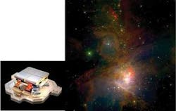
Infrared astronomy has advanced rapidly since the first two-dimensional IR-imaging arrays were produced in the 1980s. From the modest 32 × 32-pixel arrays that provided a breakthrough 20 years ago, the size of IR arrays has increased to the 2048 × 2048-pixel arrays that are now the standard in IR astronomy. Infrared arrays have greatly expanded the exploration capability of telescopes because infrared can see through the gas and dust in star-forming regions (see Fig. 1). Infrared wavelengths are also required for studying distant galaxies for which the expanding universe has shifted visible light into the IR spectrum.
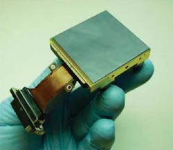
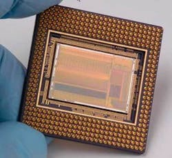
The HAWAII-2RG is Teledyne’s most advanced IR-imaging array for astronomical instrumentation and is widely used in the newest generation of instruments for ground-based and space-based observatories (see Fig. 2). The HAWAII-2RG (H2RG) is a 2048 × 2048-pixel array based on 18 µm pixel pitch that provides high quantum efficiency (QE greater than 80%) and very low noise (less than six electrons), which enables astronomers to detect and study the faint light from the most distant galaxies.Fifteen H2RG IR arrays (63 million pixels) will fly in the James Webb Space Telescope (JWST), and the H2RG is in use or planned for instrumentation at nearly every major ground-based observatory. Many instruments will use a mosaic of four H2RG arrays to provide a 4096 × 4096-pixel focal-plane array (see Fig. 1 inset).
The H2RG is the most prominent member of the evolving HAWAII family of IR imaging arrays produced by Teledyne Imaging Sensors for astronomy. The HAWAII acronym stands for mercury cadmium telluride (HgCdTe) Astronomical Wide Area Infrared Imager, and other members of the HAWAII family are the H1, H1R, H1RG, and H2. For these arrays, the H stands for HAWAII, the number 1 or 2 denotes 1024 × 1024 or 2048 × 2048 pixels, R denotes reference pixels, and G denotes guide-window capability.
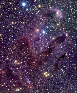
Many H1 and H2 arrays are in use at ground-based observatories (see Fig. 3). The H1R flew on the Deep Impact asteroid intercept mission and is integral to the Wide Field Camera 3 (WFC3) being installed in the Hubble Space Telescope in 2008. In addition, two mid-wave IR (sensitive to 5.2 µm) H1RG arrays will be flown in the Wide-field Infrared Survey Explorer (WISE) to launch in 2009 for an all-sky 3.5-to-23 µm IR survey.Hybrid arrays
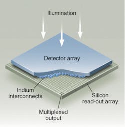
The HAWAII imaging sensors are hybrid complementary-metal-oxide-semiconductor (CMOS) arrays that combine the light-sensing capability of an IR detector material with the low noise and high functionality provided by a CMOS integrated circuit (see Fig. 4). The CMOS circuit is fabricated in the same silicon foundries that produce computer chips, but special amplifiers are required to sense the very small packets of photo charge produced by faint astronomical sources.For the IR detector material, Teledyne uses a layer of HgCdTe, slowly and precisely grown one atomic layer at a time, using molecular-beam epitaxy. A unique feature of HgCdTe is that, by varying the ratio of mercury to cadmium, we can optimize the bandgap and therefore the wavelength sensitivity of the detector layer for the scientific mission. Teledyne produces HgCdTe arrays with wavelength cutoffs for near-IR (1.7 to 2.5 µm), mid-wave (5 µm), long-wave (8 to 10 µm), and very long wave (up to 18 µm). The hybrid CMOS architecture produces pixels with 100% fill factor and high QE. As the quality of the HgCdTe material has improved, the JWST specification of dark current less than 0.01 electrons per pixel per second (at 37 K operating temperature) is achievable for 2.5 and 5 µm cut-off H2RG arrays.
The HgCdTe crystal structure is grown on a cadmium zinc telluride (CdZnTe) substrate with lattice spacing nearly identical to that of HgCdTe. When the detector layer is hybridized to the CMOS readout circuit, the substrate is on “top,” the side of the hybrid that faces the incident illumination. The CdZnTe substrate is opaque to wavelengths shorter than 0.9 µm, and hybridized arrays with the substrate are insensitive to visible light. The process for substrate removal used for the JWST, WISE, and WFC3 arrays provides several performance improvements; among them is HgCdTe sensitivity through visible wavelengths down to 0.4 µm. Quantum efficiency is higher for the “J” band (1.1 to 1.4 µm), and an antireflection coating further optimizes QE at all wavelengths. Fringing that occurs in the substrate layer is eliminated, as is fluorescence from cosmic rays absorbed in the substrate layer.
The CMOS read-out circuit for the H2RG provides several advanced performance features. Four rows and columns of reference pixels along each side of the array track any bias voltage fluctuations over the long (typically 1000 s) exposures required in astronomy. Reference pixel subtraction is key to achieving the lowest noise performance. The H2RG can intersperse readout of a guide window with readout of the entire array, so that the science array can perform the guiding function required for accurate telescope stabilization.
Another feature of the H2RG array is low noise from nondestructive readout and multiple sampling. The pixel amplifier in the H2RG is read out nondestructively, and during a long exposure, multiple subframes can be read out. For example, 96 frames will be read out during the 1000 s exposure of JWST. Because the read-out noise of each sample is uncorrelated, processing of multiple frames reduces read-out noise and can be used to eliminate the effect of cosmic rays, which deposit a large amount of charge in individual pixels. An H2RG science array can achieve less than six electrons total noise (root-mean-square) for a 1000 s exposure. Total noise is a combination of read-out noise and dark-current noise. To read out the H2RG with four read-out ports, each at 100 kHz pixel rate (10.6 s full-frame readout), the H2RG requires a very low-power operation of less than 2 mW.
Current that flows through the amplifier in the pixel of the CMOS read-out array can produce IR photons that result in an undesired background glow. The H2RG has effectively eliminated amplifier glow by read-out-circuit design and light shielding with metal layers, which enables the extremely low noise that is achieved by multiple nondestructive readout.
SIDECAR ASIC
In parallel with the development of the H2RG, Teledyne developed an application-specific integrated circuit (ASIC) that interfaces directly with the H1RG and H2RG, providing all of the functionality required from focal-plane electronics. The System for Image Digitization, Enhancement, Control and Retrieval (SIDECAR) ASIC provides significant reduction in the size, weight, and power of the focal-plane electronics (see Fig. 5).The SIDECAR contains a programmable microprocessor, bias generators, clock generators, amplifiers, and analog-to-digital converters. Up to 36 analog inputs can be accommodated in parallel, and digitized with 500 kHz, 16-bit or 5 MHz, 12-bit analog-to-digital converters, The SIDECAR interfaces digitally with instrument electronics, and with low-voltage differential-signal communication, the SIDECAR can be placed several meters from the instrument electronics. Operation of the SIDECAR is fully programmable via the communication lines.
The SIDECAR ASIC has been selected for use in three of the four instruments of the JWST. Two features of the SIDECAR were important factors in its selection for JWST. The first is low-power operation. For JWST operation, four ports continuously read at 100 kHz pixel rate and 16-bit digitization, the SIDECAR uses 11 mW of power at 37 K. Low-power operation enables JWST to place the SIDECAR within the very cold (37 K) instrument module, which is located 4 m cable length from the electronics located in the warm section of the observatory.
The second reason SIDECAR was selected for JWST is its low-noise performance. The SIDECAR noise is negligible compared to the H2RG read-out amplifier, so that the total noise of the H2RG-SIDECAR system is set by the low-noise H2RG operation.
The SIDECAR has been operating with the 4096 × 4096 IR camera at the University of Hawaii 88 in. telescope since early 2007, and the SIDECAR is being incorporated into new instruments for several ground-based observatories. Moreover, both the H2RG and the SIDECAR have undergone environmental testing for spaceflight and have passed NASA’s Technology Readiness Level 6-an important milestone for acceptance in space missions. With a high level of radiation hardness, the H2RG and SIDECAR are now being considered for other space missions.
Other wavelengths
The hybrid CMOS architecture is not limited to infrared imaging. Using a silicon p-i-n detector layer, the H2RG provides high QE and 100% fill factor in x-ray, UV, and visible wavelengths, out to the silicon cutoff of 1.1 µm. Teledyne has provided H1RG and H2RG silicon p-i-n arrays to astronomy groups that specialize in x-ray and visible imaging.
With its incorporation into many of the most advanced IR instruments for ground-based and space-based astronomical observatories, the H2RG will provide the scientific world with a wealth of high-quality infrared images and spectra of planets, stars, and galaxies in the next few years. Infrared data will produce much of the evidence that is used to understand the mysteries of dark matter and dark energy. The next ten years will be an extremely exciting time for IR astronomy and the H2RG figures to be a central player in the drama that unfolds.
James W. Beletic is director, Astronomy and Civil Space, Teledyne Imaging Sensors, 5212 Verdugo Way, Camarillo, CA 93012; e-mail: [email protected]; www.teledyne.com.
