INTEGRATING SPHERES: Baffle tubes serve as alternatives to integrating spheres
An easily constructed baffled projection tube overcomes many of the drawbacks of integrating spheres for the characterization of sensors and cameras.
ERIC NELSON
Integrating spheres have many applications in the collection and generation of light energy. A properly constructed sphere with an output port is an excellent way to generate uniform light, with the port behaving much like an isotropically radiating source of finite size. Integrating spheres also excel at uniform collection of light, leading to applications such as measuring the total energy output of lamps and luminaries. Installed inside a sphere, the total energy output of a lamp can be uniformly collected and measured.
Spheres are also used in the characterization and calibration of camera systems. Calibration is made possible by inserting the lens end of a camera into a large sphere and measuring/correcting the nonuniform brightness distribution that results from the specific lens used and the stop setting. This works well because of the isotropic distribution of ray angles within the interior of the sphere.
Irradiance/illumination applications
Although integrating spheres have a long history and presence in optical labs and have been applied in many configurations, one of their most popular applications-that of producing uniform illumination at a plane-is actually a poor match because of their inherent behavior and limitations.
For example, spheres are often used to characterize image sensors and detectors by placing the imager in the port plane of the sphere. This use is different from the common application in which an integrating sphere is used to produce an isotropically radiating plane at its port. Although the two cases are intimately related and at first glance would seem to be functionally equivalent, careful examination reveals important practical differences and limitations associated with the use of a sphere, as well as “unnatural” aspects of the irradiance field produced by a sphere at its port plane (in particular, the irradiance field is one rarely seen in the practical world, and is thus not optimal for characterizing sensors). Thus, it is worth discussing the substantial advantages and versatility of an underexamined “baffled projection tube” that can be used to produce uniformly irradiated planes.
Baffle tubes
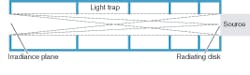
The baffled projection tube makes use of a uniformly radiating disk, such as that produced by a sphere, but instead projects the output of the disk over a specific distance to the irradiance plane in use (see Fig. 1). Projection within a tube structure serves several functions. The tube includes light traps formed by a flat-black painted surface and a baffle-plate arrangement inside the tube. The length of the tube combined with the diameter of the radiating disk determines the paraxial operating configuration of the projector (its f/number and focal length, where f/number equals the focal length divided by the diameter of the entrance pupil).

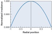
For a baffle tube, the irradiance distribution created at a plane by an isotropically radiating source of finite size can be modeled using an equation (see Fig. 2). For an f/16 projection system with a focal length of 32 in., for example, the irradiance distribution can be plotted as a function of the radial distance from the center axis (see Fig. 3). Upon examination of the equation, and recalculating for various combinations of distances and radiating disk diameters, it becomes clear that the irradiance distribution at the plane tends to be parabolic in shape, with the brightness dropping as one travels from the center of the field to the edge. If the radiating disk and irradiance plane share equal diameters, the parabolic shape becomes shallower (more uniform) with increasing distance between the disk and the irradiance plane. Conversely, the parabolic shape becomes deeper (less uniform) as the distance decreases.

null
In addition, increasing the radiating disk size will produce a shallower parabolic brightness distribution for any given distance, whereas decreasing it will impose an opposite effect for any given distance. Similar relationships are evident when calculating for different combinations. For example, one important limiting case is essentially an isotropically radiating “point source,” irradiating a plane at a given distance, while the opposite limiting case is an infinitely large radiating disk, illuminating a “point” on a plane at a given distance.
From a radiometric standpoint, the irradiance distribution equation determines the entire behavior of the baffle tube as a function of the candidate radiating disk diameter and the distance to the projection plane. The mechanical tube structure serves only to trap light that does not directly irradiate the plane, and serves as a shroud so that work can be done in lighted rooms.
Integrating-sphere drawbacks
An ideal integrating sphere would be perfectly spherical and coated, and would possess a large diameter-to-port-size ratio. In the irradiance distribution equation, the port plane of an integrating sphere defines a special case of an optical projection system in which the operating f/number and focal length are both zero. But, although the sphere can be ideal, this configuration poses several drawbacks.
Compared to baffle tubes, integrating spheres exhibit an unnatural irradiance field. Few objects in nature-or sensors and detectors under test-are exposed to irradiance fields that are isotropic over such large field angles. Cameras and lenses almost never operate this way, and even nonimaging detectors and systems are rarely configured to collect light at or near 2π steradians (180° fields). Even cameras configured with wide-angle lenses do not project irradiance fields onto the image plane over fields of view this wide.
Consequently, systematic errors often result from the specific misuse of this configuration in the testing of image sensors and/or cameras. The behavior of nearly all image sensors is very dependent on the angles of incoming rays. This applies to sensor performance parameters ranging from responsivity and uniformity, to parasitic responses, to appearance of pixel defects and other behaviors.
Conversely, use of the baffled projection tube enables the projection of more practical, real-life irradiance fields, using f/numbers actually encountered in integrating spheres, cameras, and lens systems. It allows selection of irradiance-field projections that match arbitrary real-life requirements.
Integrating spheres also suffer from alignment sensitivity. Using a sphere this way imposes a particular alignment sensitivity when placing an image sensor in the sphere port plane for testing. This configuration operates at f/0 and results in essentially no depth of field.
Very small alignment errors resulting from a noncoplanarity of the sensor plane with the sphere port plane or, if the center axis of the sensor is not coaxial with the center axis of the sphere port, will appear as brightness nonuniformity across the testing plane of the sensor. Small increases in distance from the port plane also incur increasingly deeper parabolic brightness reductions. And, during sphere manufacture, it is rare that there is any reliable mechanical reference on the sphere structure from which to control and minimize these alignment errors. Finding the sweet spot is usually left to the end user, and accomplished by trial and error.
As an alternative, baffled projection tubes typically operate at more reasonable f/numbers-although they can be configured to operate at any f/number-and usually exhibit good depth of field. This substantially reduces uniformity errors related to alignment of the detector being measured.
Uniform illumination also requires increasing sphere size. To increase the uniformity at a sphere port plane beyond what a given sphere size and port diameter can provide, requires the sphere diameter to be increased. This can quickly result in large, cumbersome test equipment.
Increasing the length of baffled projection tubes, in contrast, increases the uniformity over a given area. While excessive length may sometimes still be impractical, it is often much less objectionable than the needed increase in the diameter of a sphere.
High sphericity and coating quality are additional requirements for proper operation of integrating spheres, which often require regular recoating.
Because of their higher and more reasonable f/numbers, baffled projection tubes are easy to fabricate, do not require any expensive spherical surfaces that must be machined or turned, and are usually very insensitive to radiance nonuniformity of the radiating disk used in the projector. Complex calculations and laboratory work show that the radiating disk in a baffled projector operating at f/11 can exhibit a 25% radiance nonuniformity of the radiating disk, while still maintaining irradiance uniformity at the projection plane of better than 98%.
The difficulty of projecting into cameras and other optical systems is another drawback of integrating spheres. Spheres are often impractical or incapable of illuminating objects, such as image sensors, that are either inside or part of an optical system. In order for a sphere’s projection-field f/number of 0 to uniformly irradiate a plane, it must project directly onto the plane using all 2π steradians of the radiating port. This makes projecting a uniform field inside the front cavity of almost any camera very impractical. Vignetting inevitably results, and increases the nonuniformity of the irradiance field.
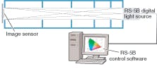
Again related to the operating f/number, baffled projection tubes can usually project directly into cameras and other optical systems, resulting in a uniformly illuminated plane within the mechanical confines of the system (see Fig. 4).
Finally, the higher cost of integrating spheres due to their associated f/number operation, and requirements for uniform coating and spherical shape, makes baffled tubes an attractive alternative.
Baffled projection tubes tend to be simple, cost-effective mechanical tube assemblies, painted with flat black paint. Fabrication and assembly tolerances are fairly loose because of their reasonable operating f/numbers and the dimensions, walls, and apertures of the tube play an indirect role in the performance of the projector. Baffled projection tubes trap unwanted light, shroud the system, and define the operating f/number of the projector. Further, they do not require an exotic coating over large areas, such as the barium sulfate coatings used in many spheres.
ERIC NELSON is a physicist at Gamma Scientific, 8581 Aero Drive, San Diego, CA 92123; e-mail: [email protected]; www.gamma-sci.com.