Illumination Systems Design: LEDs offer an attractive alternative to HID lamps in miniature projectors
Simultaneous requirements for small physical size and high-brightness output make “pocket projector” design a particularly difficult challenge.
MICHAEL ZOLLERS
Ongoing development of white-light LEDs has yielded sources that offer a unique combination of high intensity, small package size, and high electrical efficiency. These LED sources, in turn, can power more-sophisticated displays, such as ultraminiaturized “pocket” projectors. Realizing the full potential of these LEDs presents significant design challenges, however. In particular, some white-light LEDs contain discrete red, green, and blue emitters, whose output must be homogenized to achieve the desired color characteristics in the final display. Today’s digital-projector and optical-design technologies offer a variety of color-homogenization techniques that could enable the use of such LED sources.
Technology background
“Pocket projectors” are loosely defined as battery-powered projectors that fit in the palm of the hand and weigh about one pound. These highly portable projectors will enable enhanced display of mobile electronic devices, such as digital cameras, portable DVD players, laptop computers, and PDAs.
Many projectors on the market are based on the digital-light-processing DLP technology developed by Texas Instruments (Dallas, TX), while others are based on liquid-crystal-display (LCD) technology. The DLP projectors use a digital micromirror device (DMD) to spatially modulate the incident light and produce the desired image information. The DMDs are available in many resolutions and sizes, such as XGA or SVGA chips with 0.7 or 0.55 in. diagonals, respectively.
The DMD modulates light intensity but not color. With a single DMD, color display is therefore accomplished by sequentially modulating the intensity of individual colors. In most implementations, a wheel containing red, green, and blue filter segments will rotate in the light path, completing one rotation during each frame. The rapid sequential presentation of the colors is integrated by the human visual system.
Miniature projectors also require a light source with an extremely small emitting region. The smaller the source as compared to the DMD, the easier it is to efficiently collect light from the source and transfer it to the screen. For example, ultra-high-performance (UHP) high-pressure mercury lamps manufactured by Philips (Eindhoven, The Netherlands) produce around 6000 to 10,000 lumens of output, have a typical rated lifetime of 6000 hours, and utilize a very small arc gap (about 1 mm).
Achieving greater miniaturization
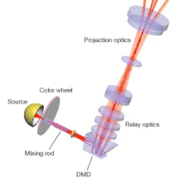
The optical elements of a typical, single-DMD-based projector include the lamp assembly, a color wheel, a mixing rod, relay illumination systems design, and a projection lens (see Fig. 1). The mixing rod performs several functions. First, it transforms the spatial distribution of the source into a more uniform spatial distribution for even illumination of the final screen image. Second, it transforms the round shape of the source output distribution into a rectangle with essentially no loss, thereby matching the aspect ratio of the DMD being used. Finally, tapered rods can be used to increase the apparent size of the source while simultaneously reducing its angular extent, matching the illumination cone angle with the projection-lens acceptance angle. Mixing rods can either be constructed from a solid transparent dialectic, which utilizes total internal reflection, or as hollow tunnels with mirrored sides.
One approach to miniaturize digital projectors is to replace the arc-lamp source and color wheel with an RGB (red, green, blue) LED array. This approach delivers several advantages. First, an LED is mechanically smaller than a UHP lamp assembly, which has an integral reflector to collect lamp output. The UHP radiates into virtually an entire sphere, while the LED emits into a hemisphere. Additionally, the smaller size and lower temperature of the LED enable it to be placed close to the mixing rod. Sequentially powering the red, green, and blue emitters eliminates the need for the color wheel. Furthermore, the typical output spectrum provided by an RGB LED can provide a broader color gamut than can be achieved with a UHP lamp. In addition, LEDs provide much higher electrical efficiency.
The main disadvantage of current LED sources is that their total output and luminance is an order of magnitude lower than that of a UHP lamp. Consequently, LED performance is an area of intense development. Another problem with RGB LEDs is that there is a spatial separation between the various color emitters. It is critical that both the spatial and angular output distributions from each of these individual emitters appear identical at the DMD; otherwise, the final displayed image will be nonuniform in color and brightness. Coupling the LED directly into a properly designed tapered mixing rod can help to efficiently mitigate these issues.
Mixing-rod modeling
It is challenging to design a mixing rod that simultaneously meets all the requirements for a compact, RGB LED-based projector. Specifically, these requirements include maximum throughput efficiency, excellent illuminance and color uniformity, good matching of the illuminated area to the dimensions of the DMD, and minimum overall package size. However, new capabilities in illumination design software have greatly simplified this process by providing the ability to create complex mixing-rod shapes with minimal effort, and optimization capabilities that can refine a design form automatically.
The design task described here was to create a mixing rod for an OSTAR Projection LED (Osram; Regensburg, Germany), which consists of a 2 x 2 matrix of individual LED emitters: one red (or “amber”), two green, and one blue. Each LED die is 1 mm square, so the total square array is just over 2 mm on each side.
Modeling this source requires duplicating its spatial and angular output distribution, as well as its spectral characteristics. The latter is important because there are specific requirements for the color temperature, or white point, of the displayed image. In this case, each LED emitter was specified to have a Gaussian spectral output distribution with a center wavelength and full-width half-maximum (FWHM) of 627 and 20 nm (red), 521 and 44 nm (green), and 460 and 24 nm (blue). The Gaussian distribution provides a good estimate of the “real” output. The ORA LightTools software can also be used to model a measured spectral distribution.
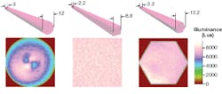
Three design forms were investigated for the mixing rod (see Fig. 2). These three tapered rods had round, square, or hexagonal ends. To create virtual prototypes of these components the user can simply specify the size and shape of the mixing rod ends, and the program automatically creates the intervening geometry specified as a straight line, Bezier, or cubic spline profile. In addition, twists and the cross section at any point can be specified to create even more-complex geometries.
The mixing rods were made of solid acrylic. The LED was essentially flush with the coupler input, which was physically large enough to accept the LED. This arrangement collects virtually the entire hemispherical output of the LED. The coupler output face was sized to produce an exiting light cone of 15 degrees, matching the f-number of the DMD and a typical projection lens.
Analysis and optimization
Because of the symmetry of the system, the uniformity of the angular or spatial distribution for one LED emitter is similar to the distribution for the other three emitters. For all three straight-tapered mixing rods, 75 mm was found to be the shortest length to achieve a reasonable level of color uniformity; in each case, longer rods can provide better uniformity. However, shorter light pipes with different shapes have recently been shown to achieve sufficient uniformity.1 Clearly, the square profile delivers the highest degree of uniformity for this length. The square profile also delivers the highest transmission efficiency (80.2%), as compared to 77.7% for the round, and 77.6% for the hexagonal rods.
It should be noted that, in each case, the illuminance distribution was analyzed over an area that exactly matches the rod end-shape, ignoring detector regions that fall outside the end-face aperture. Some analysis programs can only analyze illuminance over a square area, which leads to errors when calculating illuminance data, such as average and standard deviation, over other geometrical shapes.
The automatic optimization capability of the software can be used to optimize various system performance parameters; in this case, it was used to achieve the target white point in the final illumination distribution. To accomplish this, the program was allowed to vary the output levels for each of the individual colors to produce a color temperature of 6500 K, a typical white-point value for these types of projectors. This optimization indicated that the two green LEDs should be operated at 73% of their nominal output, the blue LED at 77%, and the red at 100%. The “true color” of the output illuminance (6500 K is displayed as somewhat blue) turns out to be quite spatially uniform.
REFERENCES
1. T. Davenport, W. Cassarly, and T. Hough. Proc. SPIE 5942, 29 (2005).
MICHAEL ZOLLERS is an optical engineer/marketing at Optical Research Associates, 3280 E. Foothill Blvd., Pasadena, CA, 91107; e-mail: [email protected]; www.opticalres.com


