Spatial Light Modulators: Liquid-crystal SLMs benefit the study of atmospheric turbulence
The versatility of liquid-crystal spatial light modulators have made them an important tool for research aimed at emulation of atmospheric turbulence and the mitigation of its effects using advanced wavefront control.
MATTHEW E. GODA, ANNA M. LINNENBERGER, JASON D. SCHMIDT, AND STEVE A. SERATI
Liquid-crystal spatial light modulators are amazingly versatile devices with many applications in optics. Their decreasing cost is making them more widely available to researchers. In recent years, students at the Air Force Institute of Technology (AFIT) have been using spatial light modulators (SLMs) to study atmospheric turbulence-a problem that profoundly impacts military laser systems. The large number of independently controllable elements in SLMs has allowed students to study turbulence in ways that were previously impossible.
Atmospheric turbulence theory
Turbulence in Earth’s atmosphere is caused by random variations in temperature and pressure that alter the refractive index of air, both spatially and temporally. As optical waves propagate through the atmosphere, the waves are distorted by these refractive-index fluctuations. Such distortions can adversely affect many types of optical systems such as those for optical communications and imaging as well as for laser-based weaponry.
During the last 100 years, modeling the effects of turbulence on optical propagation has received much attention and a focus on statistical modeling has produced several useful theories. Statistical analyses are necessary because it is impossible to exactly describe the refractive index for all positions in space and for all time-there are too many random behaviors and variables to account for in a closed-form solution. The most widely accepted theory, due to its consistent agreement with observation, was first put forward by A.N. Kolmogorov in 1941.1 His theory is the basis for all contemporary theories of turbulence.
Impact on military laser systems
If the effects of atmospheric turbulence are not compensated for, they would be catastrophic for many applications, particularly military laser systems. The effects on imaging through the atmosphere have been recognized since Isaac Newton’s time. Since the early 1980s, the U.S. Department of Defense has invested in adaptive-optics technology to overcome these degradations. For high-energy laser systems, the key effects are beam jitter (also called beam wander) and beam spreading. These effects reduce the average power delivered, thereby increasing the time to achieve the desired effect or possibly eliminating the effect altogether. For free-space laser communications, beam wander can cause significant signal fades as the beam moves, as well as significant fluctuations in received power. The use of a mechanism to compensate for atmospheric distortions, such as an SLM, has been shown to allow these missions to succeed.
Liquid-crystal SLMs
A phase modulating SLM consists of a liquid-crystal-on-silicon (LCOS) backplane, a nematic liquid-crystal layer, and a cover glass coated with a transparent electrode (see Fig. 1). The LCOS backplane is an array of aluminum pixels, which serve as both reflective mirrors and electrodes. Each electrode is an independently controllable pixel resulting in a fully programmable high-resolution phase-modulating array. Optical modulation is achieved by applying a voltage across the LC layer from the backplane pixels to the transparent electrode on the cover glass. As light enters the LC layer polarized along the extraordinary axis, the light is delayed or phase shifted. The amount of the phase shift depends primarily on three factors: the extraordinary index of the LC material, the thickness of the LC layer, and the wavelength of the input light. As an electric field is applied to a nematic LC layer, there is a corresponding reduction in the extraordinary index of the LC material, and a reduction in the phase shift induced. The index change induces a phase-only modulation of the input light.
null
Turbulence emulation
Students at AFIT have studied methods of emulating the optical effects of atmospheric turbulence in a laboratory. Emulating turbulence is necessary for testing the performance of adaptive-optics systems in a controlled environment. Two approaches have been used at AFIT. The first is to treat the atmosphere as a collection of turbulent layers. The second approach is to treat the atmosphere as a bulk medium. Each method has its advantages and disadvantages.
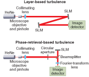
The first approach has been in use for many years using static phase plates as phase-only turbulent layers. The plates can be rotated to create a dynamic atmospheric emulator. In this approach, the turbulence strength, location, and angular speed of each phase screen can be varied to model the atmospheric parameters of interest. Recently, LC SLMs have taken the place of phase plates in some laboratories. Spatial light modulators have the advantages of being dynamic, controllable, and repeatable without moving parts. Students at AFIT have studied this approach using up to two SLMs, with each SLM representing one turbulent layer (see Fig. 2, top).2, 3 Other researchers have reported use of a single SLM to represent up to three turbulent layers. In this setup, each layer is realized on one quadrant of the SLM.4
The second approach is new and has not yet been reported in literature. Here, the only goal is to represent the optical field after it has already propagated through turbulence. For example, a wave-optics simulation could be performed and the optical field at the end of the turbulent path saved. Then a bulk turbulence-emulating system can be used to recreate that optical field in the laboratory (see Fig. 2, bottom). This method requires use of the Gerchberg-Saxton phase-retrieval algorithm to compute the phase that should be commanded onto the SLM.5 Any turbulence parameters can be used as long as the simulation is accurate. Moreover, real irradiance and phase data could be collected instead, and phase retrieval could be performed on those data so that they can be recreated.
Wavefront control
Typically, deformable mirrors (DM) are used as wavefront correctors in adaptive-optics systems. The benefits of deformable mirrors are that they can handle unpolarized broadband light and they have submillisecond response times. However, DMs are expensive and low resolution, and because of their continuously mirrored surface DMs introduce an interactuator influence. In contrast, SLMs offer many benefits. They are high resolution, currently having as many as 1024 × 1024 fully functional independently controllable pixels. Such high resolution in combination with independent pixel control allows SLMs to represent phase shifts with a much larger dynamic range than DMs. They are low cost, currently less than $0.08 per pixel for a 512 × 512 SLM. In addition, SLMs are small, lightweight, and require low power.
There are drawbacks to SLMs such as decreased diffraction efficiency, slower response times, polarization dependence, and wavelength dependence. However, some of these drawbacks can be overcome. With the addition of a dielectric stack to the backplane of the SLM diffraction efficiencies of 94% have been measured. Likewise, with the combination of new liquid crystals and a slightly higher-voltage backplane a phase modulator was built and verified to be capable of submillisecond response times. Polarization independence has been successfully demonstrated with the addition of a quarter-wave stack to the SLM backplane. This leaves the primary limitation of operation with monochromatic light only, which is acceptable for some adaptive-optics applications such as laser communications.
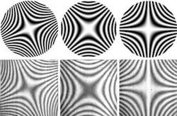
Spatial light modulators have the ability to compensate for hundreds of waves of aberration through the use of modulo-2π operation. Thus, a device with only slightly more than one wave of phase stroke can emulate large phase strokes (see Fig. 3). The benefits of small phase stroke are that the wavefront corrector is fast, compact, easy to drive, and inexpensive to fabricate. However, for this scheme to work properly the phase response of the LC must be linearized over 0 to 2π, and any backplane distortion must be calibrated out. Automatic algorithms to perform these calibrations have been developed making it possible to quickly and accurately characterize SLMs. Consequently, it has been possible to demonstrate the ability of a SLM to compensate for large higher-order zonal aberrations. Because of the modulo-2π operation of the SLM, these calibrations are optimal for one particular wavelength, limiting use of an SLM to the wavelength for which it was designed and calibrated.
Because optical modulation is not directly dependent on the backplane used, but instead on the type of liquid crystal and the liquid-crystal layer thickness, the same backplane can be used for many applications. This modular design makes SLMs versatile across a wide range of technologies such as optical correlators, beamsteerers, optical trapping and manipulation, foveated imaging, scene projectors, spectral projectors, holographic storage, and pulse shaping.
AUTHORS’ NOTE
The technical results and conclusions expressed in this article are those of the authors and do not necessarily reflect the official policy or position of the sponsors, United States Air Force, the U.S. Department of Defense, or the U.S. Government.
REFERENCES
1. A.N. Kolmogorov, in Turbulence, Classic Papers on Statistical Theory, edited by S. Friedlander and L. Topper (Interscience, New York, NY, 1961).
2. M.R. Brooks and M.E. Goda, Proc. SPIE 5553, 258 (2004).
3. J.D. Phillips, M.E. Goda, and J.D. Schmidt, Proc. SPIE 5894, 589406-1 (2005).
4. J.D. Mansell, A.A. Jacobs, and M. Maynard, Proc. SPIE 5894, 589401-1 (2005).
5. J.R. Fienup, J. Opt. Soc. A 4, 118 (1987).
6. J. C. Wyant, “Zernike Polynomials,” http://wyant.opt-sci.arizona.edu/zernikes/zernikes.htm.
MATTHEW E. GODA is an assistant professor in the Dept. of Electrical and Computer Engineering, Air Force Institute of Technology, Wright-Patterson Air Force Base, Ohio; ANNA M. LINNENBERGER is a computer engineer and STEVE A. SERATI is president and director of R&D at Boulder Nonlinear Systems, Lafayette, CO; and JASON D. SCHMIDT is a graduate student in the Electro-Optics Program at the University of Dayton, Dayton, OH; e-mail [email protected].


