OPTICS TESTING: MTF quickly characterizes the performance of imaging systems
SAMUEL SADOULET
Current trends in the optics industry require that every precision optical assembly, even those produced in large volume, be supplied with certifiable modulation-transfer-function (MTF) inline testing. This is especially true in the highly competitive automotive and cellular phone/PDA (personal digital assistant) markets. But MTF metrology has traditionally been an expensive and slow endeavor reserved for cost-insensitive low-volume projects. We have developed technology and deployed it internally to speed up our MTF measurement. We believe this technique strikes a reasonable balance between accuracy, throughput, and cost, making it practical for large-volume production quality-control environments.
Definition of MTF
The image quality of a vision system is a measure of how easily information can be extracted from the resulting image. Historically, image quality was quantified in terms of resolution-a measure of maximum object detail discernible by the system. Using resolution alone, however, is a drastic oversimplification of the forces at work. Actually, contrast-a measure of the intensity difference between the image’s black and white-also plays an important role in determining how easily information is extracted from an image. Good-quality lenses transfer more contrast at higher frequencies (that is, at a higher resolution) than do bad ones.
The ability of a system to transfer object contrast at a particular frequency is quantified by its MTF. Assuming that the object has 100% contrast, the MTF is a plot of the image contrast versus object frequency. The notion that resolution can be specified without a contrast level does not make sense. Both are cleanly incorporated into an MTF specification.
The MTF is a 2-D function typically represented by two cross sections, labeled the sagittal and tangential response (or vertical and horizontal). For a typical single field point, optical systems will focus sagittal rays differently than tangential rays. Also, in typical lenses, the center of the field of view has a higher MTF than the edges, because some optical aberrations depend on field angle. Therefore, the full field response of an imaging system is represented by several MTF curves corresponding to on-axis, some portion of the field, and full field.
Advantages of MTF
Specifying image quality in terms of MTF presents some distinctive advantages over other methods. For example, MTF is an objective measurement. Traditional methods, in contrast, primarily rely on visual testing, in which the operator gauges the quality of the lens based on observing different targets. Because humans have difficulty visually gauging contrast, visual tests typically identify the highest frequency the operator can see. Results depend on the individual operator and the operator’s fatigue level, however; in addition, this method gives no indication of contrast levels at lower frequencies, which is a problem for applications in which the contrast at lower frequencies is more important than the limiting resolution-which is true for almost all imaging applications in which the signal is sampled (such as CCD, CMOS, and CID applications).
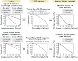
Modulation-transfer-function information is also useful for system integration, because many components within an imaging system have an associated MTF. This is true for the lens, of course, but also for the camera, capture board, cables, and so forth. Because these are cascading systems, the system MTF is simply the product of the component MTFs. In other words, the system contrast at a specific frequency is calculated by multiplying all of the component contrast levels at that frequency (see Fig. 1). As a result, MTF is a powerful method for matching up components within an imaging system to get optimal performance at the frequencies of interest.
Pressure for high volume
Imaging devices are making their way into an ever-increasing number of applications, including PDAs, cell phones, and automobiles. The PDA and cell-phone markets are evident, given that most devices will incorporate two imaging systems, one for pictures, one for video conferencing. The automotive market offers tremendous opportunity, as cars are expected to have imaging systems for anything from lane-departure detection and back-up cameras, to blind-spot detection and IR front view (see www.laserfocusworld.com/articles/245120). For these high-volume applications, MTF has become the preferred method for specifying image quality. This puts tremendous pressure on optical manufacturers to be able to guarantee lens performance, making MTF metrology a must. The problem is that there are limited options for high-speed measurements, a critical requirement to support high-volume production.
Difficulties in testing MTF
The MTF is rarely measured directly, but is usually calculated. There are several methods for calculating the MTF (see Fig. 2). Most commercially available equipment relies on calculations based either on the point-spread function (PSF) or the line-spread function (LSF). The frequency response is calculated using Fourier techniques. For this reason, one must sample the image properly. In other words, one must measure at enough points along the PSF or LSF to ensure an accurate MTF.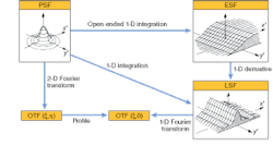
A common method for sampling the signal adequately is to introduce a microscope objective into the imaging system. For a PSF-based calculation, this has the effect of magnifying the PSF onto the sensor so that the pixels are much smaller than the PSF and can therefore reproduce it in sufficient detail. Using a microscope objective increases the maximum spatial frequency detected by the array. This enables the measurement of the MTF to frequencies well beyond the sampling (Nyquist) limit of the detector.
Another method, particularly useful for low-magnification lenses, is to place a target at the image plane of the lens and project it backward to the object plane. The detection and calculation are performed at the object plane. Once the object-space MTF is calculated, it can be converted to the image-space MTF using the magnification of the lens. This method is known as a reverse-projection MTF measurement. The advantage of this method is that it can result in high-speed measurements.
Both of these methods, however, have associated disadvantages, making them less than optimal for high-volume metrology. In systems using objectives for relaying the image, only a small portion of the field of view can be quantified at once. As a consequence, to understand the full field response of the lens, the image plane must be scanned, not only wasting precious time but also requiring a significant amount of data management. Although these methods typically result in relatively high accuracy, they clearly compromise the speed of measurement.
There are several drawbacks to the reverse-projection MTF-measurement systems. The most limiting aspect of this method is that it cannot be used for high-resolution lenses operating near 1× (0.3× to 3× or so). It is also difficult to implement for wide-field-of-view lenses without compromising some amount of accuracy. This method is clearly fast but has limitations in the range of lenses that it can test.
Using blur
In recognizing the advantages and limitations of currently available techniques, it became clear that we should develop our MTF metrology using an alternative method. We chose to base our technique on a traditional edge-response-function (ERF) calculation. By taking the derivative of the ERF, one obtains the LSF, from which the MTF can be calculated. The traditional technique still suffers from the sampling issues discussed above. For this reason, a microscope objective is commonly integrated into the imaging system, resulting in an image scan and lower-speed measurement.
Instead of an ERF- and LSF-based calculation with an integrated microscope objective, we can simply tilt the edge with respect to our pixel geometry to produce a blur function (see Fig. 3). This skewed measurement has the effect of introducing a “magnification factor” without the need for an objective. There are two analogous explanations for this magnification factor. First, introducing a skew is effectively stretching out the edge response so that the fine details can be detected. The tilt, in some respects, shifts and resamples the edge. The result is no longer a true ERF, but rather a blur function. For the second explanation, consider a global and a local (with respect to the edge) coordinate system. Although the pixel pitch (inverse pixel spacing) is constant in the global reference system, tilting the edge changes the local pixel pitch. So, effectively, the CCD array is being used only at spatial frequencies much lower than its Nyquist limit (measured in the global coordinate system.).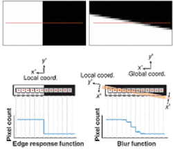
The significant deviation from traditional techniques is that the MTF is not calculated from the ERF of the lens, but rather from the blur function. The blur function of the lens has a unique relationship to the MTF of the lens and the angle of edge tilt. This technique is a natural extension of methods and the underlying principle described in the ISO 12233 and ISO 15529 documents created by the International Organization for Standardization (Geneva, Switzerland).
The advantage of using the blur function is that the measurement depends far less on the sampling of the detector. Thus, the MTF can be measured at frequencies much higher than the detector’s Nyquist limit without requiring a microscope objective. This means that the image can be fully characterized without scanning, resulting in a significantly faster measurement speed. We further developed some of these principles to enable us to extract the sagittal and tangential performance of the lens across the full field.
The hidden advantage of this method is that it is extremely well suited for measuring the MTF of a system. As we noted earlier, many components within an imaging system have an associated MTF, the product of which is the system MTF. This assumes perfect focus, which is clearly not guaranteed. This method can be used to assess how well a lens and sensor have been assembled.
Our process (patent-pending) can be used to quantify the MTF of imaging components and to guarantee the system MTF performance of subassemblies-a powerful application for companies that integrate electro-optic imaging systems. We are in advanced discussions to license this technology to a party interested in creating a product that uses this method.
Our initial research and tests led us to modify traditional techniques used to quantify the MTF of imaging lenses and systems. The advantage of this method is a significant increase in speed of measurement while maintaining adequate accuracy and repeatability. The cost for implementation is extremely reasonable, making this technique ideal for high-volume production quality control.
Samuel P. Sadoulet is director of product development at Edmund Optics, 101 E. Gloucester Pike, Barrington, NJ 08007; e-mail: [email protected]; www.edmundoptics.com.